
Multistage tuning-tolerant equalizer filter

a multi-stage, equalizer filter technology, applied in the field of data communication, can solve the problems of not being suited for low voltage operation nor small chip area implementation, not being able to achieve low-voltage operation, etc., to achieve enhanced tuning tolerance, improve the robustness and data-restoration capability of equalizer filters, and improve the effect of high frequency attenuation behaviour

Active Publication Date: 2009-07-21
VRIJE UNIV BRUSSEL
View PDF12 Cites 6 Cited by
  • Summary
  • Abstract
  • Description
  • Claims
  • Application Information

AI Technical Summary

Benefits of technology

The present invention provides an equalizer filter and system for compensating a received distorted signal for frequency dependent signal modifications introduced by a transmission channel. The equalizer filter has a unique design that allows for compensation of a received signal by amplifying and saturating the signal using a gain that is monotonically rising in frequency. The gain control means can be adjusted to compensate for signal modifications introduced by different transmission channels. The equalizer system can include a limiting amplifier and a comparator means for adjusting the higher frequency gain of the amplifying compensation stages. The equalizer filter can be incorporated into an equalizer system for compensating a received distorted signal. The technical effects of the invention include improved equalization of signals introduced by various transmission channels and overcompensation up to 3 dB.

Problems solved by technology

This known method makes multiple tuning signals in circuitry using many comparators and is relative complex.
It is not suited for low voltage operation nor for implementation on a small chip area using small transistors that have large input offset mismatches.
However, by limiting the amount of higher frequency gain to maximum +8 dB per tuning function, and by having only one tuning function active at a time the resulting deterministic jitter remains tolerable.
A difficulty with the above-mentioned state-of-the-art adaptive and self-adaptive equalizer filters and systems is that they estimate the losses in the channel and then compensate these losses by matched complementary amplification.

Method used


Image

  • Multistage tuning-tolerant equalizer filter
  • Multistage tuning-tolerant equalizer filter
  • Multistage tuning-tolerant equalizer filter

Examples


first embodiment

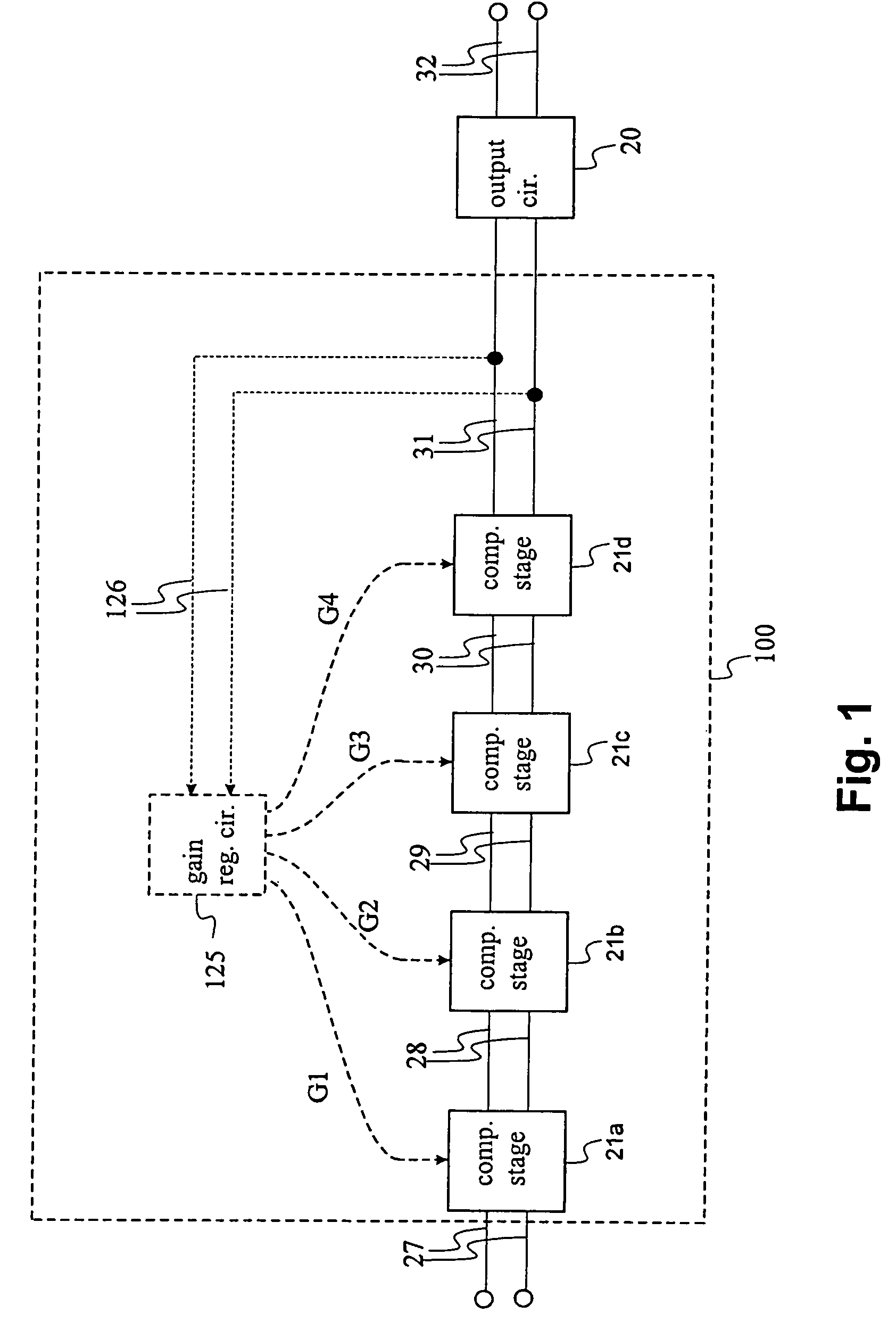
[0072]In a first embodiment, the invention relates to an equalizer filter 100 as schematically shown in FIG. 1 which achieves an allowable overcompensation with a limited amount of jitter. Jitter is the unwanted variations of a binary signal's leading and trailing edges. It occurs as the signal is processed or transmitted over a transmission channel from one point to another. Jitter also is a time displacement, either periodic or random, of a signal's switching edges. Excessive jitter always increases the bit-error rate (BER) in the transmission system. As a result, most serial data-communications systems have jitter standards that must be met to ensure robust performance and the quality of service (QoS) expected in today's networks. The filter may be used in a suitable electronic device, e.g. in a modem or receiver of a telecommunications device.

[0073]The equalizer filter 100 shows a cascade of amplifying compensation stages 21a, 21b, 21c, 21d of a multi-stage equalizer system. The...

third embodiment

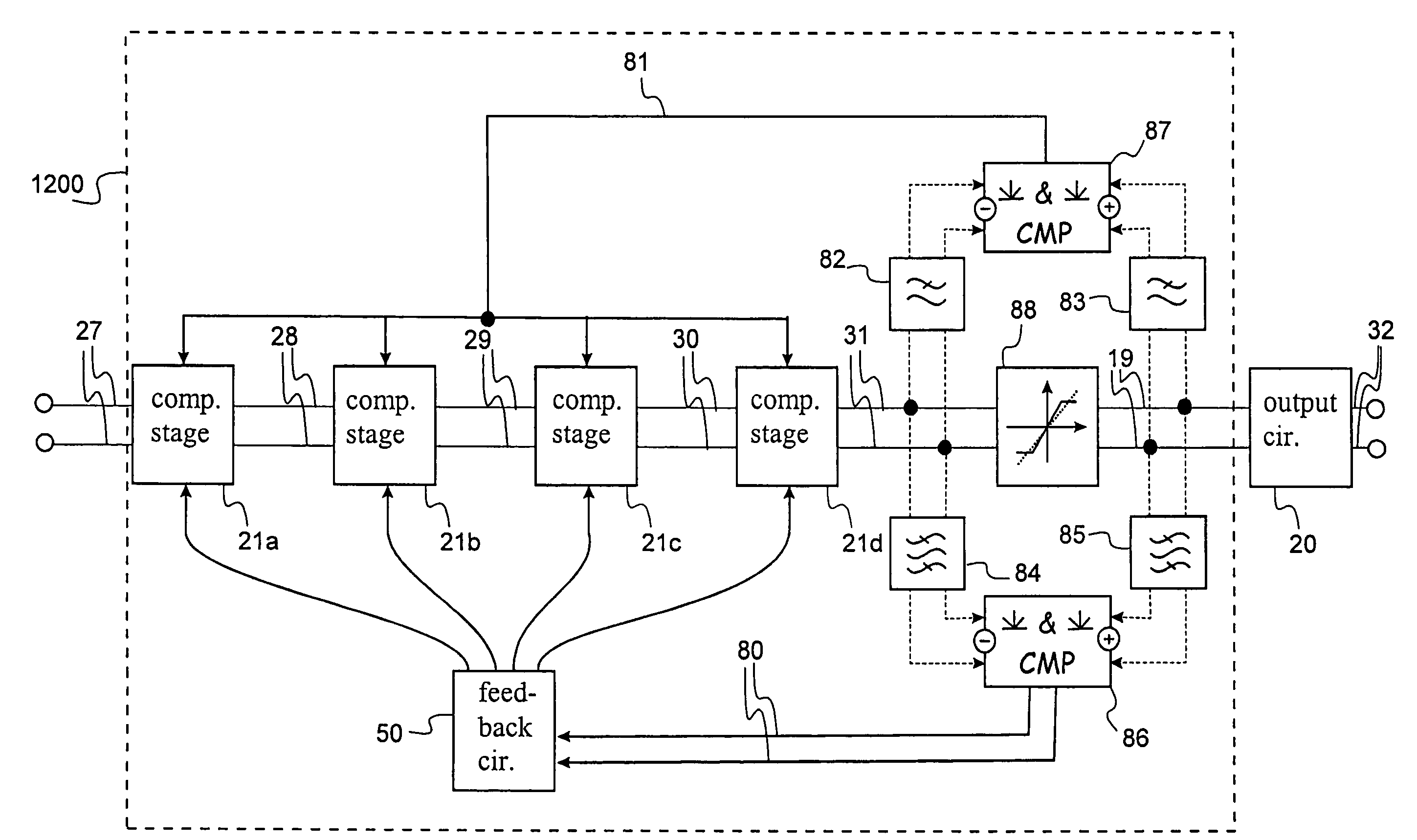
[0083]In a third embodiment, the invention relates to a wide range self-adaptive equalizer filter 500. The wide range self-adaptive equalizer filter 500, as shown in FIG. 7 is very robust. The equalizer filter 500 comprises the same components and features of an equalizer filter 100, 300, 400 according to any of the previous embodiments, but the equalizer filter 500 furthermore comprises a second feed-back loop for self adaptation. This second feed-back loop comprises a feed-back circuit 502 and a feed-back connection 504 between an intermediate node 28, 29, 30, 31 positioned after an amplification compensation stage, preferably after the last amplification compensation stage 21d, and the feed-back circuit 502. The feed-back circuit 502 preferably sequentially turns on amplifying compensation stages 21a to 21d until typically matched compensation is reached. For matched compensation typically an error margin of about 1 to 2 dB, depending on the level of compensation and compensation...

fourth embodiment

[0084]In a fourth embodiment, the invention relates to a self-adaptive equalizer filter 600 as shown in FIG. 8, wherein a large overcompensation is allowed. The equalizer filter 600 comprises the same components and has the same features of the self-adaptive equalizer filters shown in the previous embodiments, but furthermore, the input signal at input node 27 of the equalizer filter 600 is measured and fed to a feed-forward circuit 602 through feed-forward connection 604. Depending on the amplitude or power of this input signal, feed-forward circuit 602 can determine how many of the available amplifying compensation stages 21a, 21b, 21c, 21d will be turned on and will show higher frequency gain. The achievable higher frequency gain with this system is similar as with the previously described system. Due to the presence of hysteresis in the present equalizer filter 600 having a feed-forward circuit 602, the stability of the system will be improved.


PUM


Abstract

A multistage equalizer filter for compensating a received distorted signal having an amplitude for frequency dependent signal modifications introduced by a transmission channel includes at least one amplifying compensation stage having a gain and a saturation level, the gain being monotonically rising for at least a last decade in frequency below an upper data frequency of the received signal, and a gain control device for controlling the gain of the amplifying compensation stage such that the amplitude of the received signal amplified in the at least one amplifying compensation stage remains below the saturation level of the amplifying compensation stage. The gain may be regulated by separately regulating low frequency gain, mid-frequency gain and higher frequency gain for each of the at least one amplifying compensation stages.

Description

[0001]This application is a continuation-in-part of application Ser. No. 11 / 177,339, filed Jul. 11, 2005.TECHNICAL FIELD OF THE INVENTION[0002]The present invention relates to the field of data communication. More particularly, the present invention relates to devices and corresponding methods for multistage equalizer filtering in a line equalizer system, which restore the attenuated signals transmitted over a communication or transmission channel for a wide variety of communication or transmission channels with an acceptable amount of jitter. The present invention also relates to the use of the equaliser in communications system, e.g. in a modem.BACKGROUND OF THE INVENTION[0003]An equalizer system in general compensates frequency dependent losses that a signal experiences when passing through a transmission channel. Transmission channels include, but are not limited to, a wire, a pair of wires, an optical fibre, the reading and writing channels of a storage device like a hard-disc ...

Claims


Application Information

Patent Timeline
Patent Type & Authority Patents(United States)
IPC IPC(8): H03H7/30H03G5/00H03H7/40H03K5/159
CPCH04B3/141H04L25/03878H04B3/145
Inventor KUIJK, MAARTENMAILLARD, XAVIER
Owner VRIJE UNIV BRUSSEL
Learn More