Method and device for removing a cover from a storage box

a storage box and cover technology, applied in the field of storage box cover removal, can solve the problems of complex and laborious devices of this type, not always ensuring that the top cover is securely gripped, and requiring a large amount of space, so as to reduce the adhesive strength of the cover, simple design, and operation reliability.

Inactive Publication Date: 2009-07-28
GRONINGER
View PDF12 Cites 7 Cited by
  • Summary
  • Abstract
  • Description
  • Claims
  • Application Information

AI Technical Summary

Benefits of technology

[0004]The object of the present invention is to create a method of the type stated initially, which enables removal of a cover from a storage box in a reliable manner under sterile conditions.
[0005]Due to the fact that the adhesive strength of the cover is reduced in the region of a few of the sealed edges, e.g., just the transverse edges, and the cover is removed from the storage box by peeling it off, reliable removal of the cover is attainable and, in fact, without the risk that the cover will tear or not be removed completely, whereby this method requires only a small amount of mechanical outlay. The invention makes use of the knowledge that adhesive bonds have the least amount of resistance to separation by peeling, therefore making it possible, with great advantage, to carry out peeling with a small amount of force and in a reliable manner without the risk of tearing, even when storage box covers are involved. It is advantageous when the reduction in the adhesive strength of the cover takes place in the region of a seal of a few of the sealed edges, e.g., the transverse edges. The reduction in the adhesive strength of the cover can be accomplished in an advantageous manner via warming at least in the region of a few of the sealed edges, e.g., the transverse edges. It can be advantageous when the cover is acted upon from above by heating energy, in particular radiant heat, acting upon the region of a few of the sealed edges, in particular the transverse edges, at the least.
[0006]A further advantageous configuration provides that the cover is acted upon with a suction force and is removed from the storage box using this suction force. It can be advantageous when the cover is acted upon with a suction force at least in the region of a transverse edge and is removed from the associated transverse edge of the storage box using the suction force at least in the region of this transverse edge. The cover is peeled off in an advantageous manner by rolling it off of the storage box. It is advantageous when the cover is separated from the storage box by peeling it off in the region of the sealed edges, the storage box being held down while this is taking place. The peeling away of the cover by rolling it up is initiated simultaneously with the application of the suction force, whereby the cover can be rolled onto a roller positioned above the storage box. The suction force can be applied using suction devices, for example, in particular suction cups, located lengthwise in at least one row on the roller, with suction openings or the like which are connected to a vacuum source. The cover, which has been removed from the storage box and rolled up, can be unrolled in the opposite or same direction of the rolling-up, outside the region of the storage box and, as a result of the suction force being reduced, is released and dropped through a discard opening.
[0007]In this manner, a lid-like top cover, which is sealed to the storage box at the edges, is capable of being removed in a reliable, fast and economical manner under sterile conditions.
[0010]In this case it is advantageous when, in continuous sequence as the storage boxes are conveyed along, a first cover is removed in a first step by reducing the adhesive strength of the cover in the region of a few sealed edges, in particular the transverse edges, and peeling it off of the storage box and, in a subsequent, second step, a second cover which is contained loosely in the storage box is removed from the storage box. It can be advantageous when the removed and rolled-up first cover and, therefore, at least nearly simultaneously therewith, the removed and rolled-up second cover are unrolled preferably in opposite directions, outside the region of the storage box, and, as a result of the particular suction force being reduced, they are dropped through the same discard opening. By using this method to discard the covers, they can hang down nearly vertically very close together and be dropped into the same discard opening below; the discard opening can be narrow in size due to the closeness of the covers. From the discard opening, the items are then sent to the outside through a channel, a slot or the like, for example.
[0011]A further object of the present invention is a device for removing at least one cover from a storage box. Further advantageous features and embodiments of the present invention result from the related subclaims. This device enables sterile handling by utilizing placement inside an isolator. No manual handling by operating personnel is required, since the device enables automatic, continuous operation. The device is compact, simple, operationally reliable, and economical due to its simple design.

Problems solved by technology

A device of this type is complicated and laborious, requires a great deal of space, and is very expensive.
In addition, using a device of this type does not always ensure that the top cover will be gripped securely, e.g., because the cover, which extends a few mm past the edge of the storage box and only at the edges, is often bent upward or downward and therefore cannot be gripped securely.
Nor can it be ruled out that the cover will tear while it is being pulled off and will not be removed completely.

Method used


Image

  • Method and device for removing a cover from a storage box
  • Method and device for removing a cover from a storage box
  • Method and device for removing a cover from a storage box

Examples


Embodiment Construction

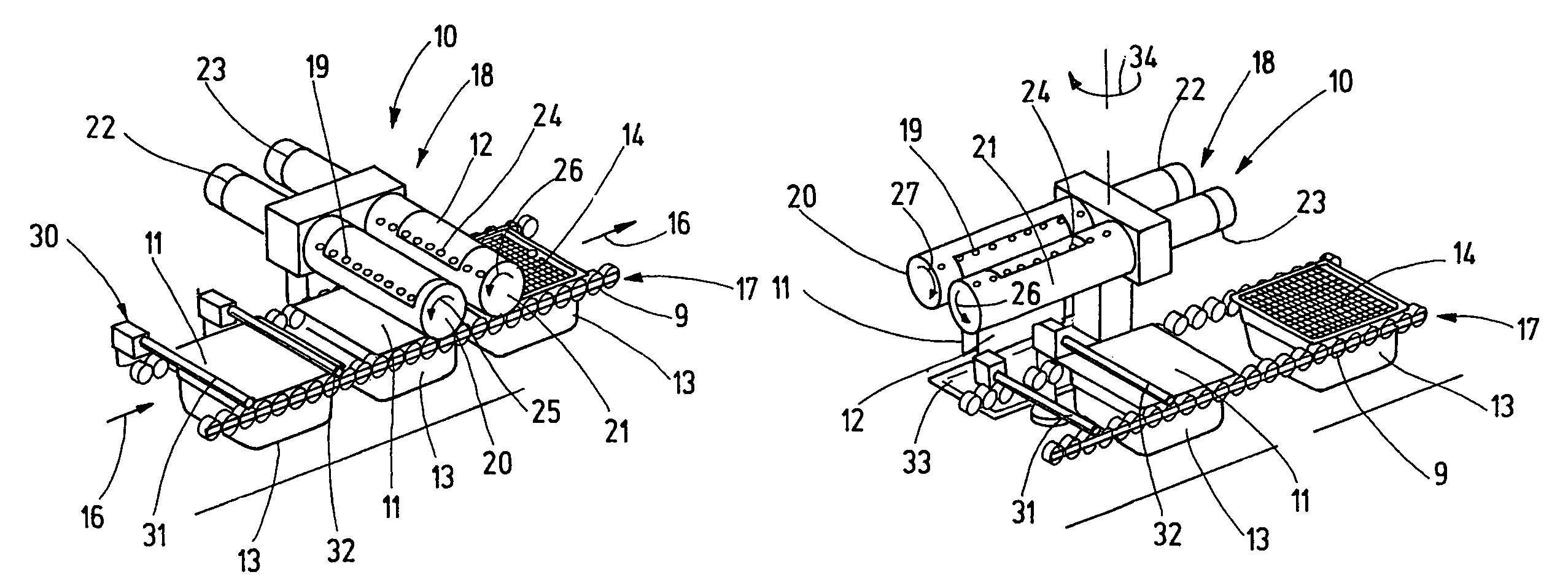
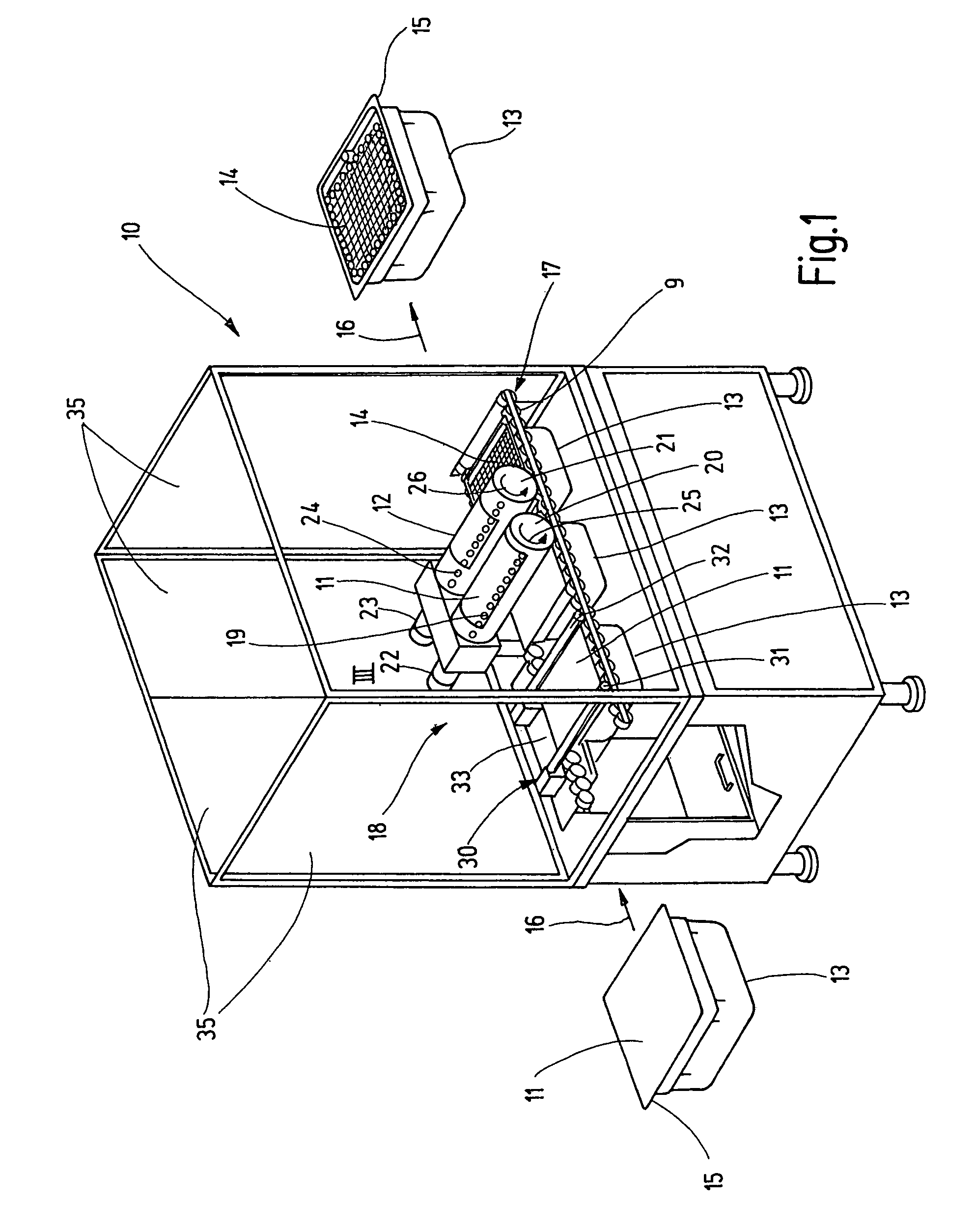
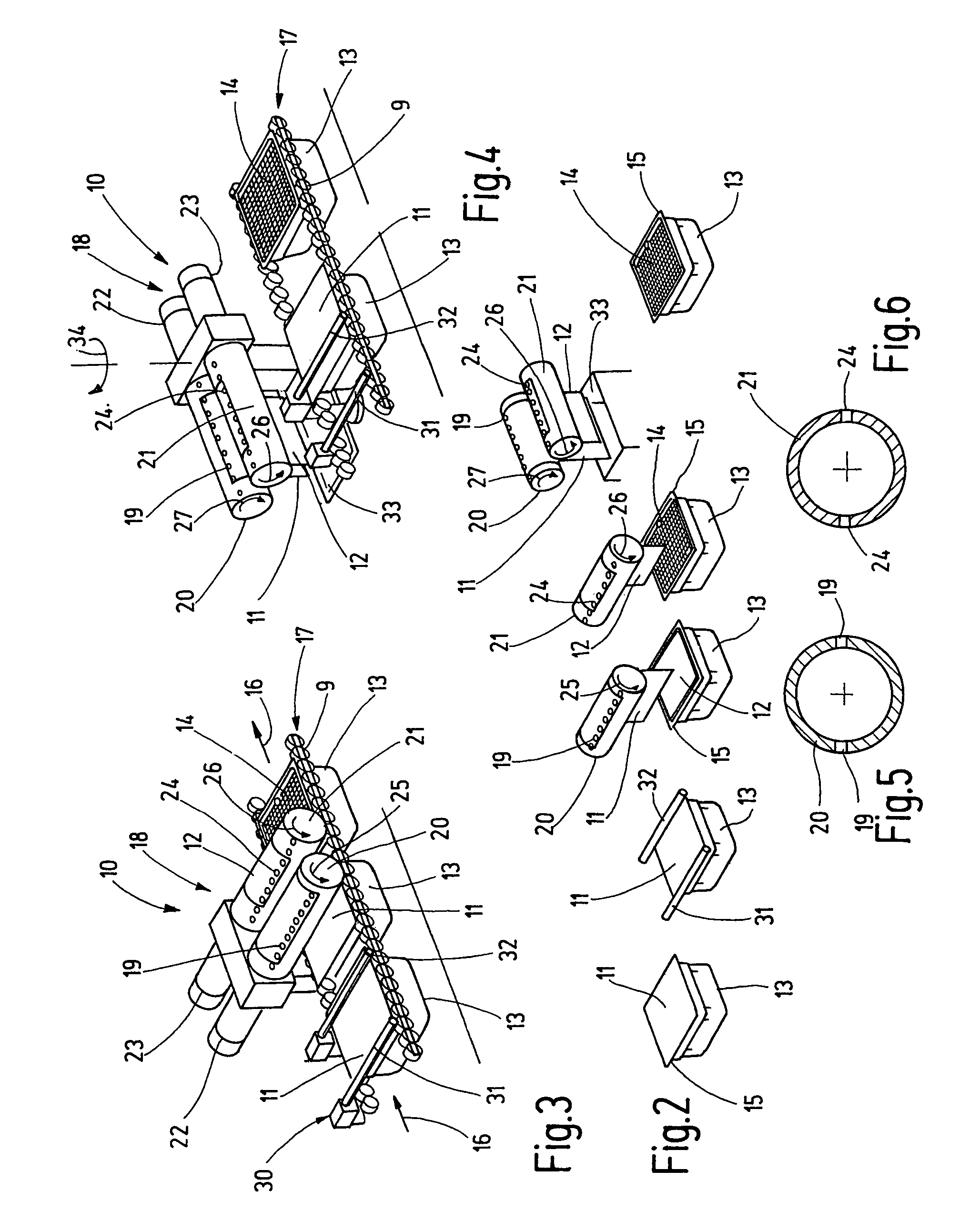
[0017]The drawing shows a device 10 designed for removing at least one cover 11 and 12 from individual storage boxes 13. These storage boxes 13 are preferably storage boxes which are filled with prefabricated disposable syringes 14 which have not yet been filled. They are positioned such that they hang in storage box 13, e.g., in a perforated tray which sits loosely on a ledge projecting circumferentially from the side walls of storage box 13. After being filled, storage boxes 13 are closed with a lid-like cover 11 which is joined via sealing with circumferential edge 15 of storage box 13. Cover 11 and this seal along edge 15 must be germ-proof, whereby cover 11 must still be detachable from edge 15 without cover 11 tearing or splitting and leaving parts of it behind. In addition, cover 11 must be designed such that disposable syringes 14 can be sterilized through it, usually using steam-based or gaseous sterilizing means. Each storage box 13 is often provided with a second cover 12...


PUM

PropertyMeasurementUnit
adhesive strengthaaaaaaaaaa
resistanceaaaaaaaaaa
rotationaaaaaaaaaa

Abstract

The present invention relates to a method and a device for removing a cover from a storage box that is closed using a lid-like cover attached thereto at the edges. For removal, the adhesive strength of the cover is reduced in the region of a few of the sealed edges and the cover is then removed by peeling it off the storage box, whereby the cover is peeled off by rolling it onto a roller.

Description

BACKGROUND OF THE INVENTION[0001]The present invention concerns a method for removing a cover from a storage box, in particular from a storage box filled with prefabricated, disposable syringes.[0002]Typically, prefabricated, disposable syringes, for example, are transported in storage boxes in which they are secured in a hanging arrangement in a perforated tray. The tray sits loosely on a ledge projecting from the inner circumference of the storage box. After the disposable syringes are inserted, the top side of each storage box is closed with a lid-like cover which is connected with the circumferential edge of typically nearly rectangular storage boxes. The connection and the cover itself must be germ-proof. In addition, a second cover is placed loosely underneath this first cover before the first cover is installed, e.g., for cushioning purposes or the like. The storage boxes are sterilized in this state and, in fact, on the exterior and the interior through the cover, so that th...

Claims


Application Information

Patent Timeline
Patent Type & Authority Patents(United States)
IPC IPC(8): B65B43/30B65B43/40B65B69/00
CPCB65B69/0025B65B69/00
Inventor MIKSCH, RUPERT
Owner GRONINGER
Why Eureka
Try Eureka