
Connection system for plastic web fencing

a connection system and web technology, applied in the field of plastic web fencing, can solve the problems of inconvenient installation and maintenance, poor connection effect, and tendency to weather and rot, and achieve the effect of quick and easy connection to on

Inactive Publication Date: 2009-07-28
JOHN WALL INC
View PDF35 Cites 14 Cited by
  • Summary
  • Abstract
  • Description
  • Claims
  • Application Information

AI Technical Summary

Benefits of technology

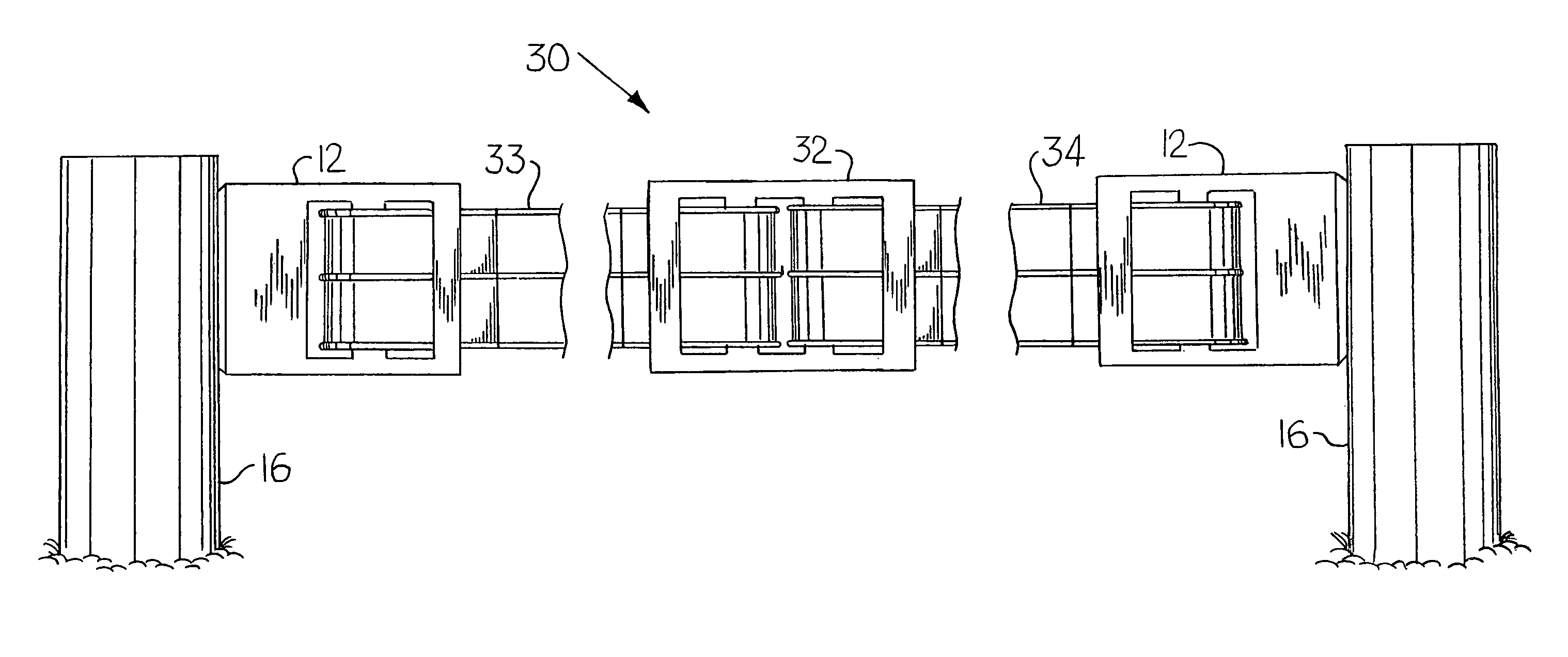
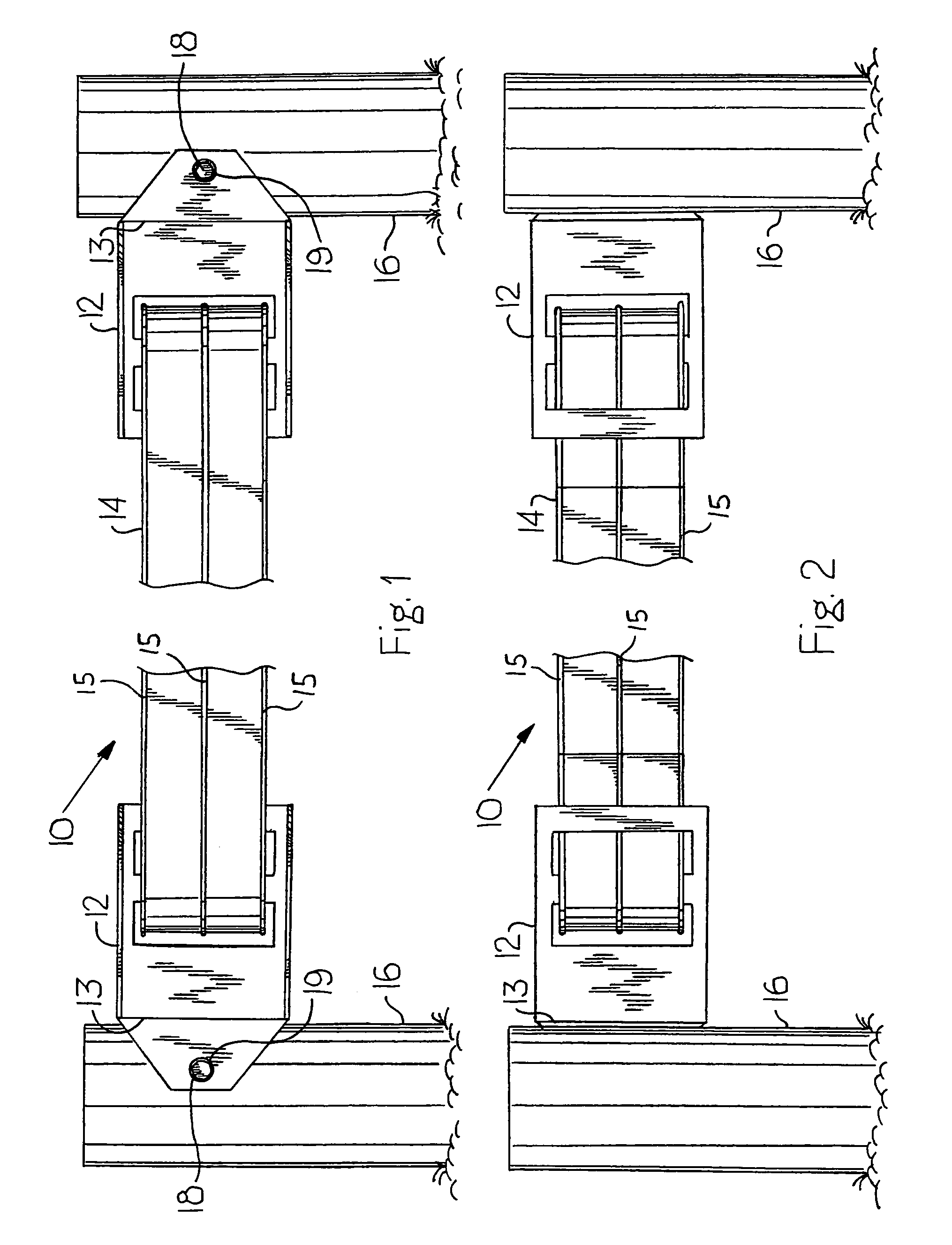
[0007]The present invention is directed to a plastic web fencing system, which requires minimal tools when installing the rail on the posts. Additionally, the plastic web fencing system may accommodate the rails at angles that conform to an uneven terrain. In addition to securing the rails to fence posts, the present invention also allows the rails to be quickly and easily attached to one another to create a single, continuous rail, without the use of any tools.

Problems solved by technology

Wood suffers from the disadvantages that it is expensive to install and maintain and, further that it has a tendency to weather and rot over time.
However, barbed wire fencing suffers from the disadvantage that its sharp barbs may cut or gouge the hide of valuable livestock animals, such as horses.
Nor does the Sura patent appear to address the problems of connecting composite metal and plastic fencing to fence posts, or joining two ends of such fencing in between posts.
Also, some of the embodiments in the Robbins patent actually puncture the fence rail, which could lead to premature deterioration of the rail.
Furthermore, the connection systems disclosed in both the Robbins patent and the Sura patent do not easily conform to uneven terrain over which the plastic web fencing may be deployed.
For example, if fence posts need to be introduced on a hillside, the connection systems in the above-discussed prior art are not able to provide the necessary angles that would keep the ribbon on the same plane as the ground surface.

Method used


Image

  • Connection system for plastic web fencing
  • Connection system for plastic web fencing
  • Connection system for plastic web fencing

Examples


Embodiment Construction

[0019]For purposes of the description hereinafter, the spatial or directional terms, such as “bottom”, “front”, “back”, “left”, “right”, and derivatives thereof, shall relate to the invention as it is oriented in the drawing figures. However, it is to be understood that the invention may assume various alternative variations, except where expressly specified to the contrary. It is also to be understood that the specific apparatus illustrated in the attached drawings, and described in the following specification, is simply an exemplary embodiment of the invention. Hence, specific dimensions and other physical characteristics related to the embodiments disclosed herein are not to be considered as limiting.

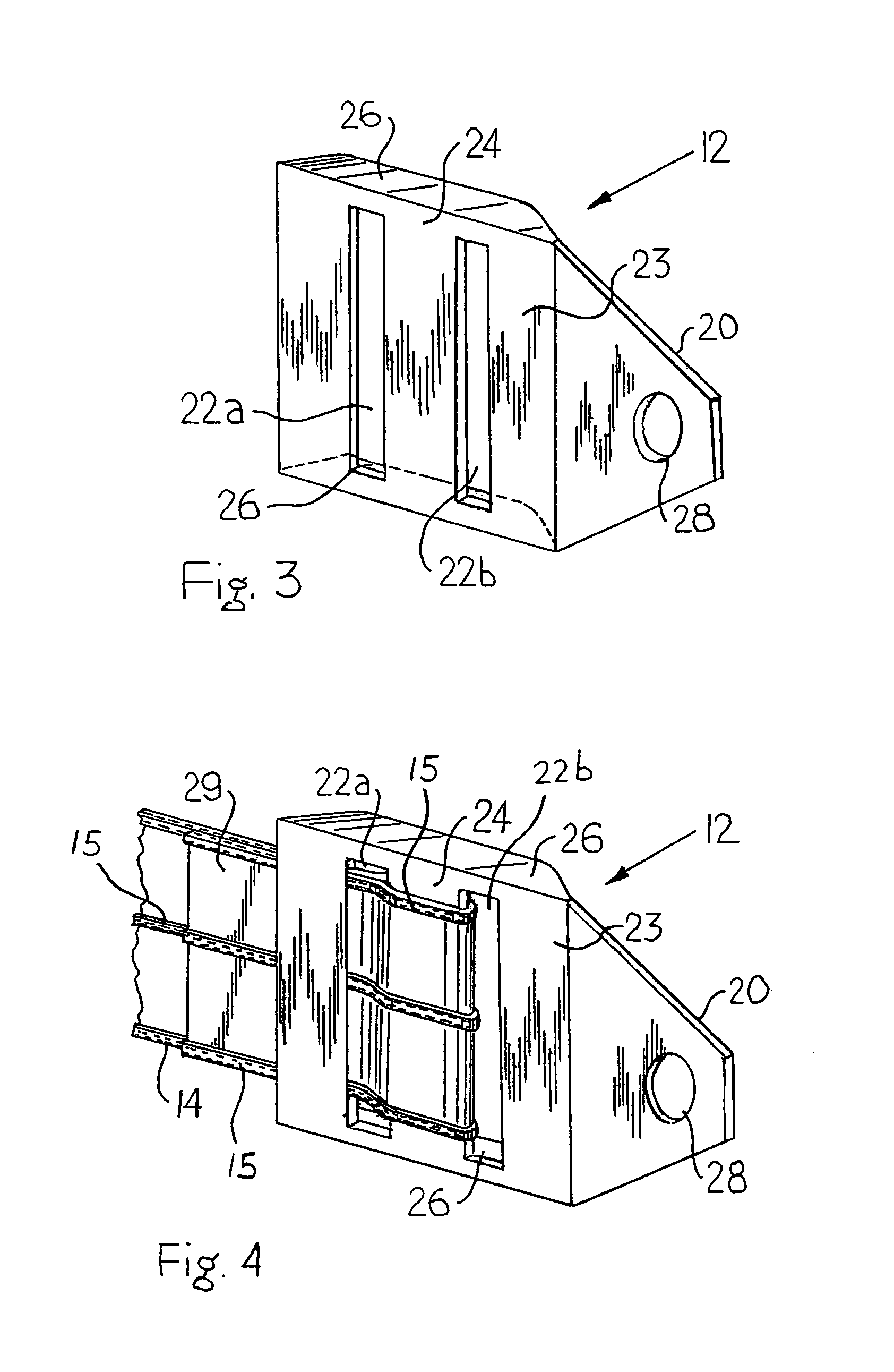
[0020]Referring now to the drawings in detail, FIGS. 1 and 2 show a plastic web fencing system 10 according to a first embodiment of the present invention. The first embodiment plastic web fencing system 10 includes one or more end connectors 12, a rail 14, one or more fence posts 16...


PUM


Abstract

A fencing system includes a rail having at least two metal wires ensheathed in a plastic web, an end connector having a face plate with two slots and a middle portion separating the two slots, the end connector having a front side and a rear side. A free end of the rail is disposed in the slotted end connector so that the rail runs from the front side of the connector through a first slot, around the middle portion, and then back through a second slot. A fastener pivotally attaches the end connector to a fence post. Also, a joining connector of similar construction as the end connector is used to secure the free ends of two rails.

Description

BACKGROUND OF THE INVENTION[0001]1. Field of the Invention[0002]The present invention relates to plastic web fencing and, more specifically, to methods and devices for securing plastic web fencing to end fence posts and for joining two ends of web fencing in between posts.[0003]2. Description of Related Art[0004]Composite metal and plastic fencing is well-known in the art. Plastic web fencing is typically constructed of two metal wires spaced a distance apart and ensheathed in plastic, with the plastic forming a web area extending between the wires. Plastic web fencing is known as an inexpensive and safe alternative to other commonly employed materials used in the construction of fences, such as wood and barbed wire. Wood suffers from the disadvantages that it is expensive to install and maintain and, further that it has a tendency to weather and rot over time. Barbed wire fencing is a relatively low cost means for enclosing livestock areas. However, barbed wire fencing suffers from...

Claims


Application Information

Patent Timeline
Patent Type & Authority Patents(United States)
IPC IPC(8): E04H17/02A01K3/00E04H17/10E04H17/14
CPCA01K3/00E04H17/1413E04H17/10E04H2017/1452E04H17/1452E04H17/124
Inventor WALL, JOHN R.
Owner JOHN WALL INC
Learn More