Turbine seal plate locking system

a technology of sealing plate and turbine, which is applied in the direction of blade accessories, waterborne vessels, machines/engines, etc., can solve the problems of limiting the effect of raising the efficiency and power output of the turbine, the shaft rotation, and the increase of the difficulty of assembly operation

Inactive Publication Date: 2009-07-28
SIEMENS ENERGY INC
View PDF25 Cites 32 Cited by
  • Summary
  • Abstract
  • Description
  • Claims
  • Application Information

AI Technical Summary

Problems solved by technology

The expansion of the working gas through the rows of rotor blades and stationary vanes in the turbine assembly results in a transfer of energy from the working gas to the rotating assembly, causing rotation of the shaft.
Thus, a limiting factor in raising turbine efficiency and power output is the physical capability of the rotor blades in relation to the temperatures within the turbine.
In such an arrangement multiple parts must be manipulated during assembly, increasing the difficulty of the assembly operation, and maintenance difficulties may arise during disassembly due to breakage of the bolts.

Method used


Image

  • Turbine seal plate locking system
  • Turbine seal plate locking system
  • Turbine seal plate locking system

Examples


Embodiment Construction

[0019]In the following detailed description of the preferred embodiment, reference is made to the accompanying drawings that form a part hereof, and in which is shown by way of illustration, and not by way of limitation, a specific preferred embodiment in which the invention may be practiced. It is to be understood that other embodiments may be utilized and that changes may be made without departing from the spirit and scope of the present invention.

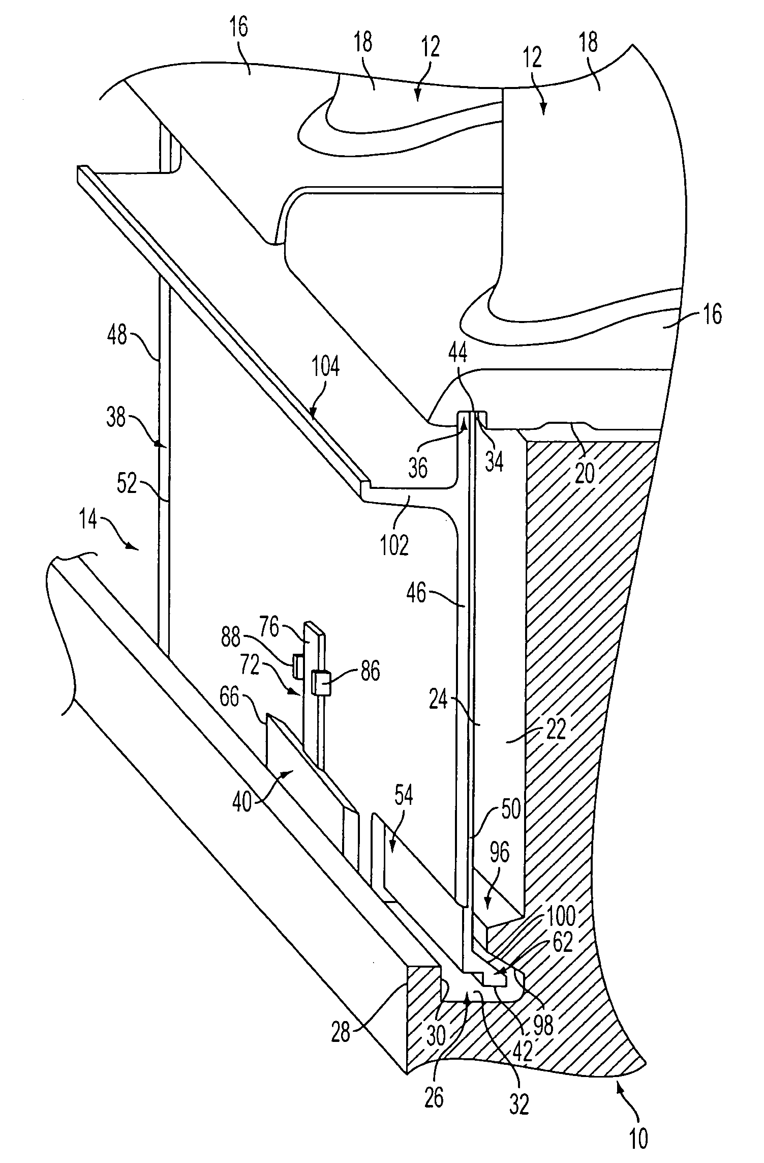
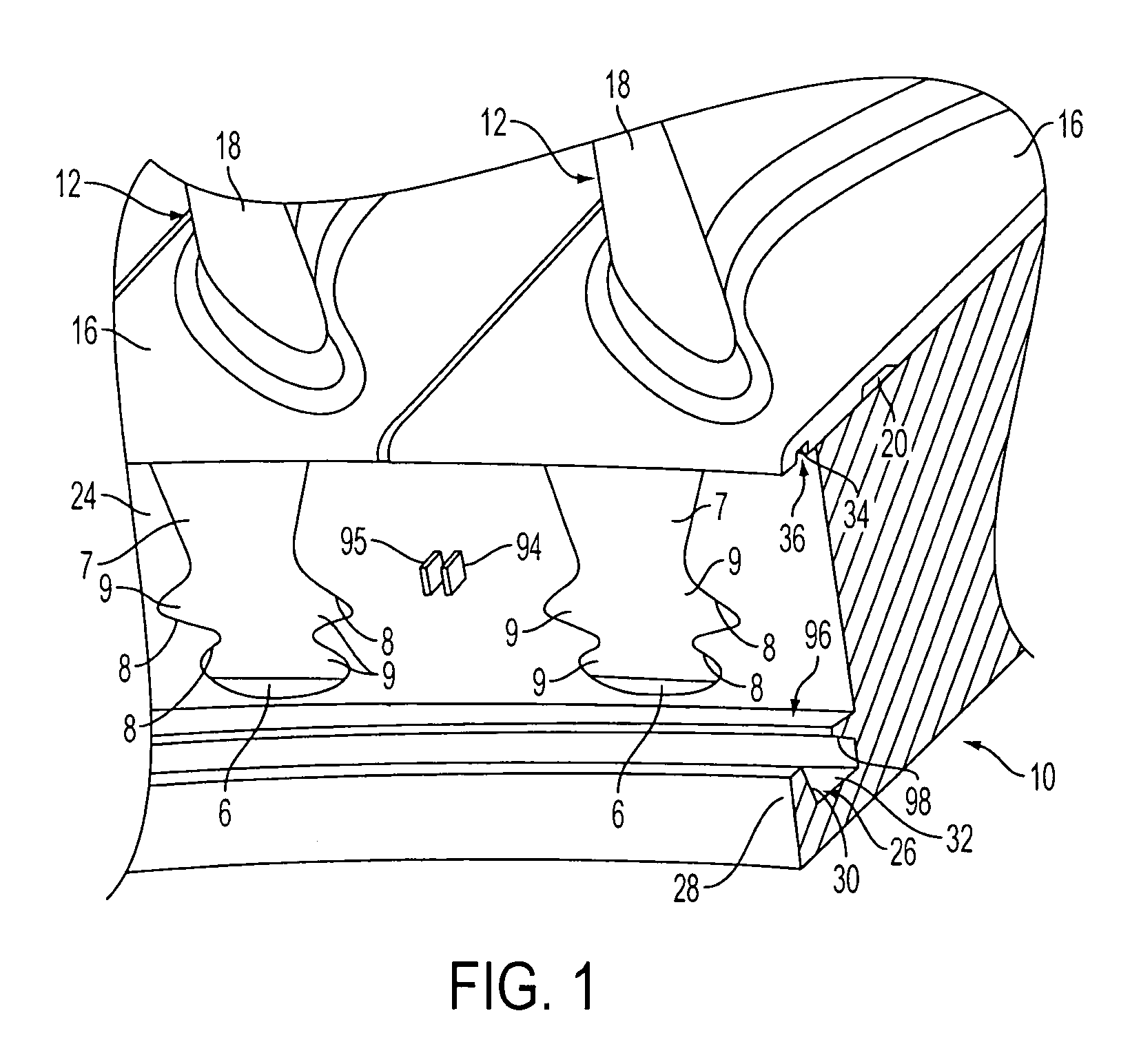
[0020]FIG. 1 illustrates a basic construction of part of a turbine rotor in a turbine assembly for a combustion turbine engine, such as a gas turbine engine, and in particular illustrates an outer peripheral portion of a disc 10 for the rotor. It should be noted that although the portion of the disc 10 illustrated in the figures appears as a disc segment, the disc 10 is preferably formed as a substantially continuous ring structure within the turbine assembly.

[0021]The disc 10 defines peripheral blade mounting sections comprising axially...


PUM

PropertyMeasurementUnit
temperatureaaaaaaaaaa
transfer of energyaaaaaaaaaa
inlet operating temperaturesaaaaaaaaaa

Abstract

A seal plate assembly is provided in a rotor disc for a turbine engine. The seal plate assembly includes a radially extending flange on the disc and an annular groove defined between a radial surface on the flange and a face of the disc. An annular outer surface extends axially in facing relationship to an annular inner surface of the groove. A plate structure is supported between the inner and outer surfaces, and a lock structure is provided for holding the plate structure in place. The lock structure includes an axial leg that is adapted to be located between an inner edge of the plate structure and the inner surface of the groove, and the lock structure further includes a radial leg that is adapted to be located between the radial surface on the flange and an outwardly facing surface of the plate structure.

Description

FIELD OF THE INVENTION[0001]The present invention relates generally to turbine blades and, more particularly, to a structure for providing a seal at the axial end face of a rotor disc for a gas turbine engine.BACKGROUND OF THE INVENTION[0002]Generally, combustion turbines have three main assemblies, including a compressor assembly, a combustor assembly, and a turbine assembly. In operation, the compressor assembly compresses ambient air. The compressed air is channeled into the combustor assembly where it is mixed with a fuel. The fuel and compressed air mixture is ignited creating a heated working gas. The heated working gas is typically at a temperature of between 2500 to 2900° F. (1371 to 1593° C.), and is expanded through the turbine assembly. The turbine assembly generally includes a rotating assembly comprising a centrally located rotating shaft supporting rotor discs and a plurality of rows of rotating rotor blades attached thereto. A plurality of stationary vane assemblies i...

Claims


Application Information

Patent Timeline
Patent Type & Authority Patents(United States)
IPC IPC(8): F01D5/32
CPCF01D5/081F01D5/3015F01D5/326F01D11/006F01D11/00Y10T29/49321F05D2260/30Y10T29/4932
Inventor BRILLERT, DIETERBERTSCH, ORAN
Owner SIEMENS ENERGY INC
Why Eureka
Try Eureka