
Board mounted structure of vibration motor

a vibration motor and surface mounting technology, applied in the field of surface mounting of vibration motors, can solve the problems of affecting the quality of vibration motors, so as to improve the fastening pattern of printed circuit boards.

Inactive Publication Date: 2009-07-28
SANYO SEIMITSU
View PDF24 Cites 6 Cited by
  • Summary
  • Abstract
  • Description
  • Claims
  • Application Information

AI Technical Summary

Benefits of technology

[0010]A second object of the present invention is to provide a board mounted structure of a vibration motor enabling improvement of the degree of parallelism of the vibration motor with respect to a flat bottom surface even when providing a raised bottom recess in the flat bottom surface and forming a solder reservoir there for fastening.
[0012]When setting a vibration motor by automatic mounting on a printed circuit board with a fastening pattern and power feed patterns coated with cream solder, a certain degree of deviation will occur in the positioning between the flat bottom surface of the metal holder frame and the fastening pattern or the external terminal pieces and the pair of power feed patterns. In the molten state of cream solder due to loading in an electric furnace, a force component of the surface tension due to the molten solder acts to pull toward the center line not only at the superposed part between the flat bottom surface and main fastening pattern surface, the superposed part between the pair of front projecting pieces and the pair of front extending pattern surfaces, and the superposed part between the pair of external terminal pieces and the pair of power feed patterns, but also the superposed part between the back projecting piece and the back extending pattern surface entering between the pair of power feed patterns, so alignment of the center line of the flat bottom surface and center line of the fastening pattern by self alignment becomes easy, deviation of positioning can be suppressed, and the yield is improved.
[0013]Further, the metal holder frame has a raised bottom recess formed in a flat bottom surface and a support part formed by bending the front end of the back projecting piece. The top surface of the raised bottom recess, the top surface of the support part, and the bottom surface of the motor case preferably are formed abutting against each other. This support part can enter between the pair of external terminal pieces and support the motor case at the end cap side, so the degree of parallelism of the motor axial line of the vibration motor body with the flat bottom surface of the metal holder frame and the fastening pattern of the printed circuit board can be improved.

Problems solved by technology

(1) In automatic mounting picking up a vibration motor and mounting it on a printed circuit board, a certain amount of deviation occurs in the positioning between the flat bottom surface of a metal holder frame and the fastening pattern or the pair of external terminal pieces and the pair of power feed patterns. In the process of melting, then cooling the cream solder for fastening by loading in an electric furnace, sometimes the axial line of the motor (center line of flat bottom surface) and center line of the fastening pattern will not be aligned and a drop in the yield will be incurred.
(2) If raising the fastening strength of the vibration motor on a printed circuit board by providing a raised bottom recess in the flat bottom surface and forming a solder reservoir there for fastening, the bottom surface of the motor case of the vibration motor will abut against the top surface of this raised bottom recess, so the degree of parallelism of the vibration motor body with respect to the flat bottom surface and fastening pattern is liable to become off.

Method used


Image

  • Board mounted structure of vibration motor
  • Board mounted structure of vibration motor
  • Board mounted structure of vibration motor

Examples


Embodiment Construction

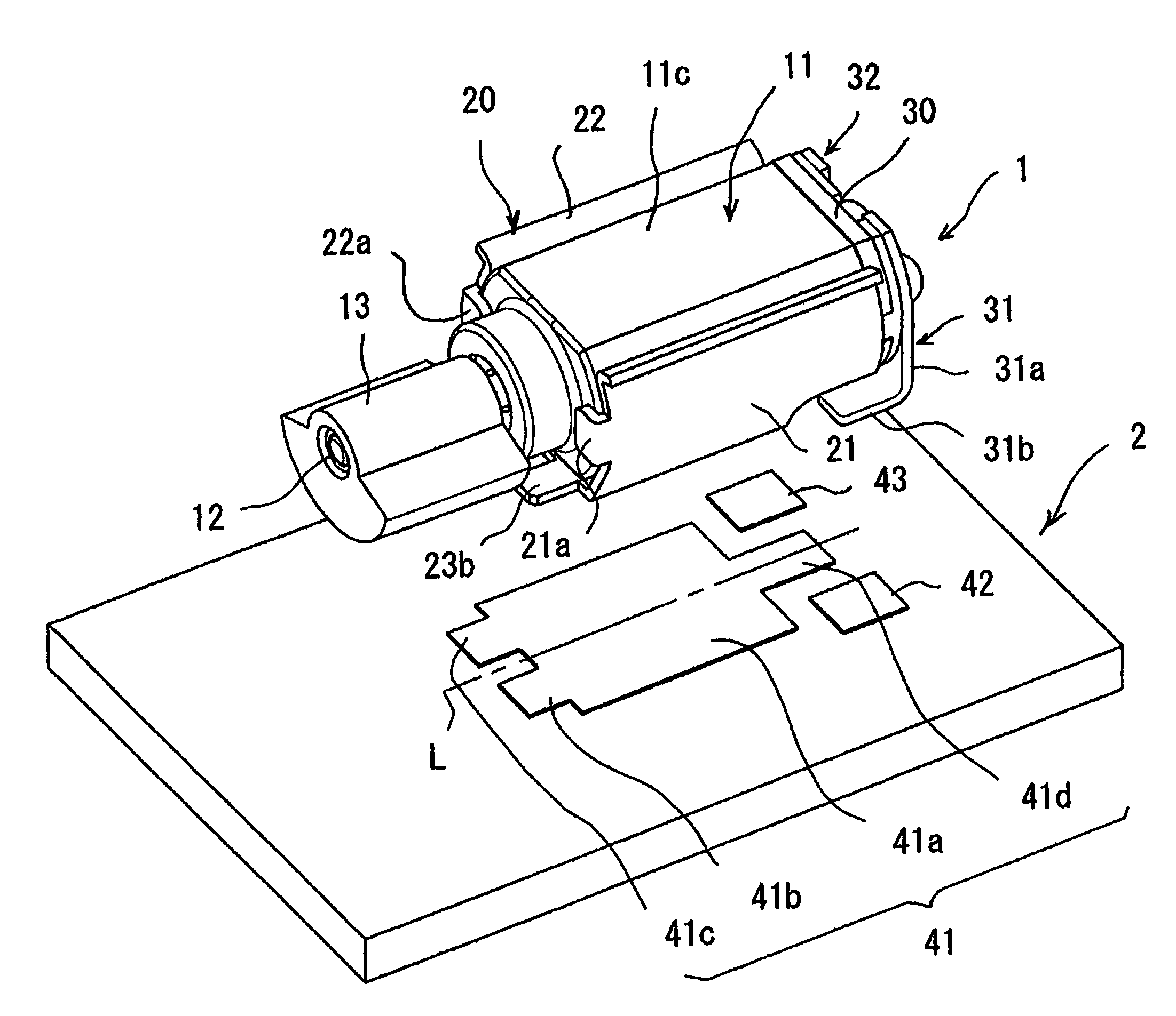
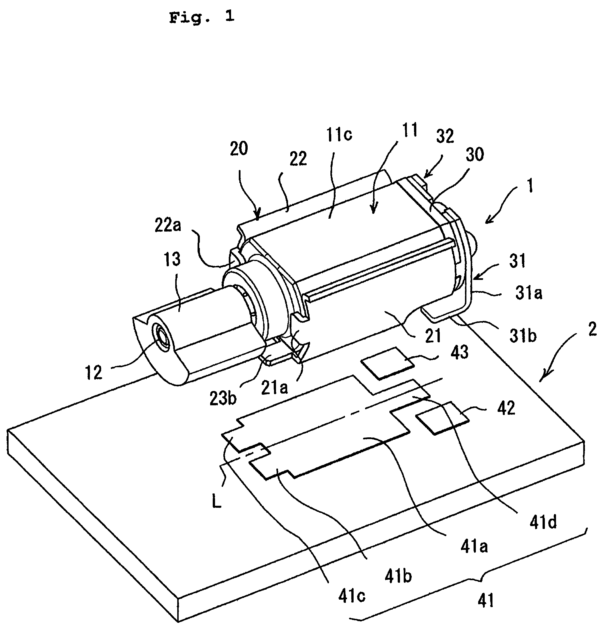
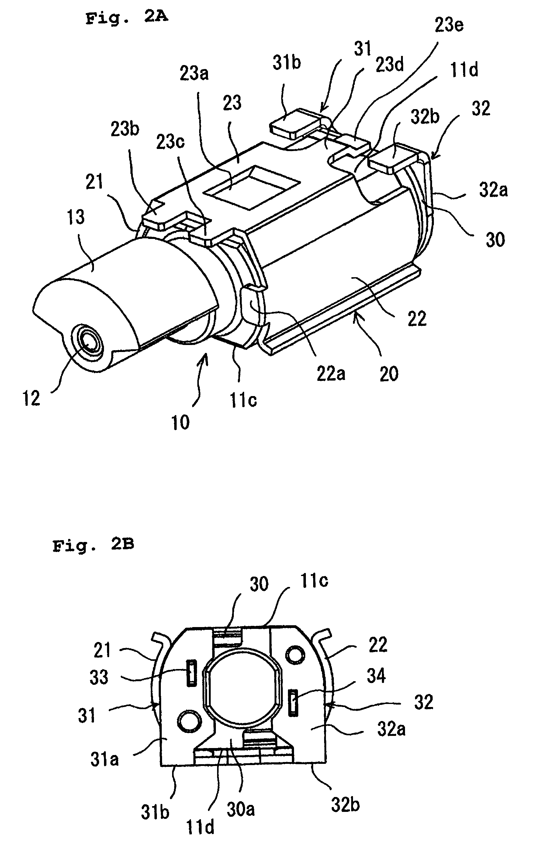
[0023]FIG. 1 is a perspective view showing the state of mounting a vibration motor according to an embodiment of the present invention on a printed circuit board, FIG. 2A is a perspective view showing the state when viewing the vibration motor from the back, FIG. 2B is a back view showing the side of the vibration motor at the opposite side of the eccentric weight, FIG. 3 is a disassembled perspective view of the vibration motor, and FIG. 4 is a disassembled perspective view of the vibration motor seen from the back.

[0024]The vibration motor 1 of this example, as shown in FIG. 1 to FIG. 4, has a vibration motor body 10 attaching an eccentric weight 13 to a motor shaft 12 projecting out from a small sized motor case 11; a metal holder frame 20 provided with a motor holding part S in which curved side surfaces 11a, 11b of the motor case 11 are held by clamping plates 21, 20; and a pair of external terminal pieces 31, 32 attached to a plastic end cap (end bracket) 30 sealing the openin...


PUM


Abstract

A board mounted structure of a vibration motor which self aligns along with melting of cream solder even if deviation occurs in positioning of the flat bottom surface of a metal holder frame and a fastening pattern at the time of automatic mounting, that is, a board mounted structure having a vibration motor having a metal holder frame into which a motor case is fit and a pair of external terminal pieces attached to a plastic end cap and a printed circuit board having a fastening pattern shaped left-right symmetric about a center line and superposed with a bottom surface of the metal holder frame and power feed patterns adjoining this fastening pattern, arranged left-right symmetrical with respect to a center line, and superposed with corresponding external terminal pieces, the metal holder frame having front projecting pieces and a back projecting piece at its flat bottom surface, the fastening pattern having front extending pattern surfaces superposed with corresponding front projecting pieces and a back extending pattern surface superposed with the back projecting piece at its main fastening pattern surface.

Description

BACKGROUND OF THE INVENTION[0001]1. Field of the Invention[0002]This application is based upon and claims a priority of Japanese Patent. Application No. 2007-204120, filed Aug. 6, 2007, the contents being incorporated herein by reference.[0003]The present invention relates to the surface mounting of a vibration motor on a printed circuit board by reflow soldering.[0004]2. Description of the Related Art[0005]As a vibration motor of a structure suitable for surface mounting on a printed circuit board, for example, as disclosed in Japanese Patent. Publication No. 11-234943-A, there is known one having a vibration motor body attaching an eccentric weight to one end of a motor shaft, a metal holder frame provided with a motor holding part holding this vibration motor body by engagement with a motor case, and a pair of external terminal pieces attached to a plastic end cap (end bracket) sealing the opening of the motor case on the side opposite to the eccentric weight, wherein a flat bott...

Claims


Application Information

Patent Timeline
Patent Type & Authority Patents(United States)
IPC IPC(8): H02K7/065B06B1/16
CPCH02K5/225H02K7/061H05K3/341H05K2201/10969H05K2201/1009Y02P70/50
Inventor TAKAGI, TAKAHIRONAKAMURA, MASATO
Owner SANYO SEIMITSU
Learn More