Eureka AIR delivers breakthrough ideas for toughest innovation challenges, trusted by R&D personnel around the world.

Method and arrangement for control of direct current motor

a direct current motor and control method technology, applied in the direction of vehicle seats, dynamo-electric motors/converters, starters, etc., can solve the problems of inability to precisely control the fan, the difficulty of accurately controlling the temperature on the seat surface, and the rise of audible dissonance from the motor

Inactive Publication Date: 2009-07-28
KONGSBERG AUTOMOTIVE AB (SE)
View PDF14 Cites 1163 Cited by
  • Summary
  • Abstract
  • Description
  • Claims
  • Application Information

AI Technical Summary

Benefits of technology

[0021]The invention has certain advantages. Firstly, a flexible solution is obtained with effective coordination from a central control unit, and a complete fan control unit is obtained that receives control information from a central control unit. In addition, a low cost is achieved as a result of the two-wire control of the fan unit. In addition, a more controlled seat temperature is obtained for a vehicle seat as the speed of rotation of the fan is controlled in response to the temperature in question, and a more controlled seat temperature is obtained for a vehicle seat as a heating element is controlled in association with the said fan. An additional advantage of the invention is that it is possible to control the fan motor at very low speeds of rotation, which is particularly advantageous in vehicle seats, not least because the application requires relatively large motors (in order to be able to provide a high output), which are difficult to run at low output. This problem is solved by means of the invention.
is that it is possible to control the fan motor at very low speeds of rotation, which is particularly advantageous in vehicle seats, not least because the application requires relatively large motors (in order to be able to provide a high output), which are difficult to run at low output. This problem is solved by means of the invention.

Problems solved by technology

A problem with previously-known arrangements for forced ventilation of vehicle seats is the difficulty in obtaining an accurately controlled temperature at the surface of the seat.
This design does not, however, allow any precise control of the fan for obtaining as accurately controlled a temperature as possible at the surface of the seat.
Normally, switching frequencies are used that are within the approximate range 20 Hz-200 kHz, which can mean that audible dissonance from the motor arises or that electrical interference arises caused by the pulse width modulation.
A disadvantage of previously known general technology for direct current motors is that a large amount of cabling is required in order to achieve both the transmission of signals and the transmission of power.
This is also associated with disadvantages associated with the need to use pulse width modulation with a high pulse frequency in order to avoid audible dissonance that originates from the pulse width modulated supply, as this gives rise to problems with electromagnetic interference, commonly given the abbreviation EMC (ElectroMagnetic Compatibility), caused by the high frequency of the switched signal.

Method used


Image

  • Method and arrangement for control of direct current motor
  • Method and arrangement for control of direct current motor
  • Method and arrangement for control of direct current motor

Examples


Embodiment Construction

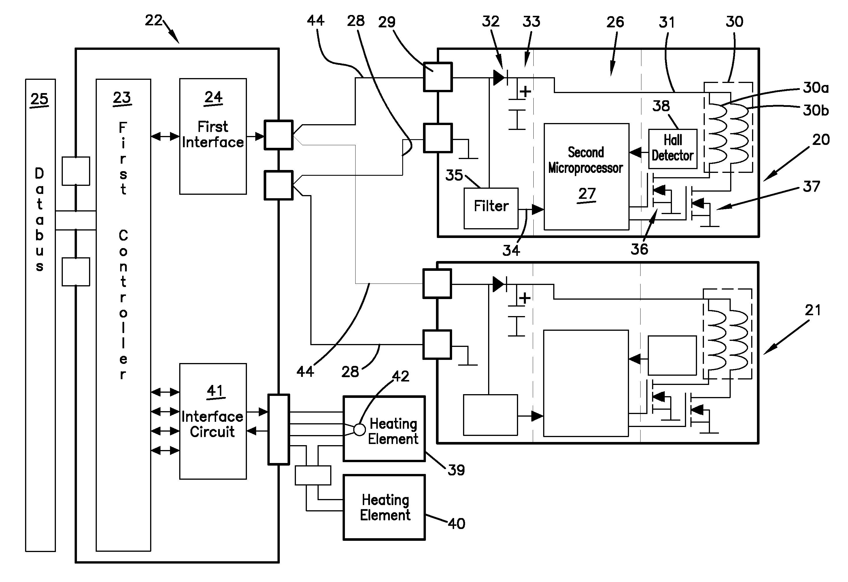
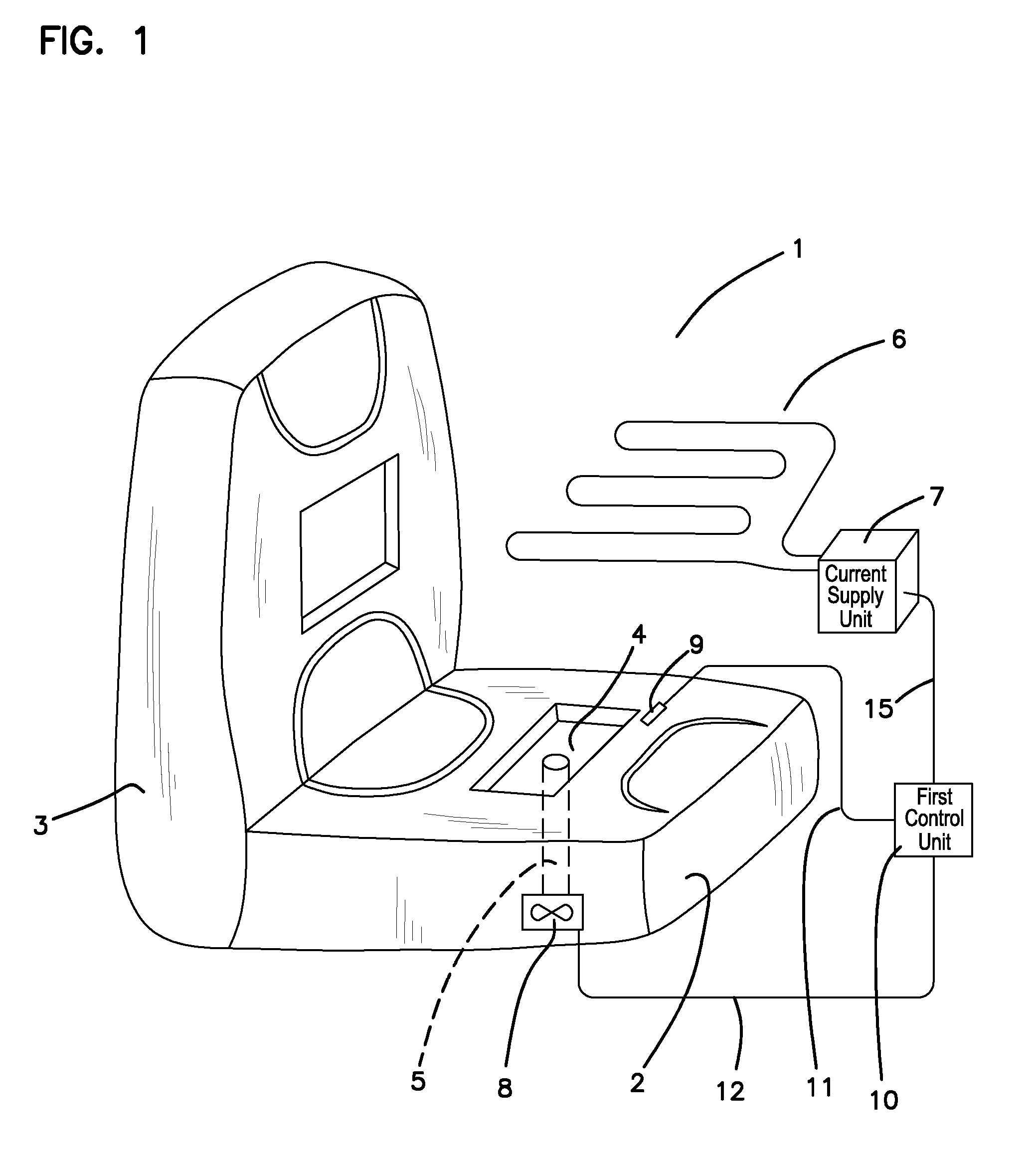
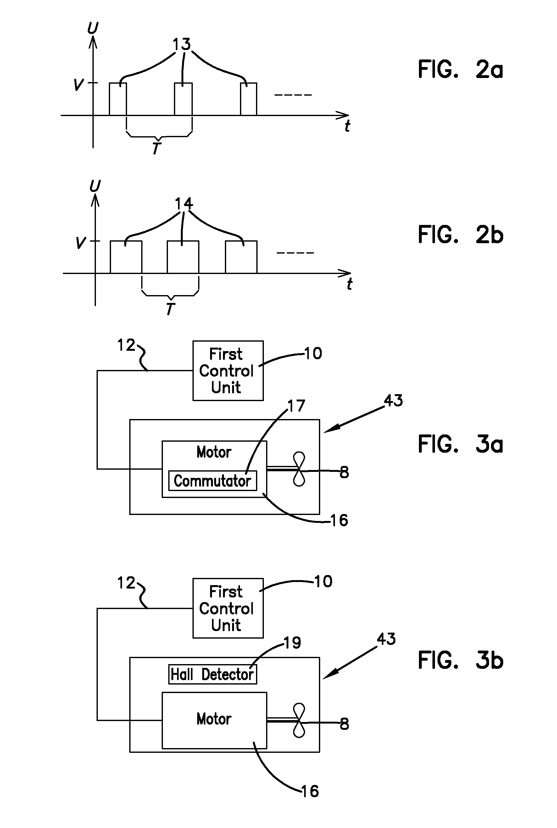
[0029]The present invention will now be described in greater detail, firstly with reference to FIG. 1.

[0030]For increased comfort, the seat cushion 2 and seat back 3 of a vehicle seat 1 can be equipped for ventilation and temperature control of the surfaces or areas upon which a driver or passenger in the vehicle is expected to sit. In the following, the seat cushion 2 will be described, but a corresponding description can, of course, apply for the seat back 3. In a vehicle, both the driver's seat and the other seats can be equipped for ventilation by blowing or extraction of air. The blown or extracted air is distributed via at least one opening 4 that is arranged in the seat cushion 2. In the case of the blowing of air, this blown air is led through a duct 5 in the seat cushion 2 and out towards the person who is sitting on the seat in question, via the distributing opening 4. In the case of the extraction of air, this extracted air is led away from the person who is sitting on th...


PUM


Abstract

The present invention relates to a method for control of a direct current motor in one or several fan units, each comprising a fan, which method comprises: generation of a control signal from a first control unit which is external in relation to the said fan unit; transmission of the said control signal to the said fan unit; reception of the transmitted control signal in the said fan unit; interpretation of the said control signal in a second control unit which is arranged in association with the said fan unit; and generation, in the said second control unit, of a supply signal for the said direct current motor, on the basis of the control signal generated by the first control unit and received in the fan unit and on the basis of a supply voltage. According to the invention, the method comprises transmission of the control signal together with the supply voltage over a shared communication link, with the control signal being superposed on the supply voltage. The invention also relates to an arrangement for such control. By means of the invention, improved control is obtained of a motor that can be utilized in a ventilated seat in a vehicle.

Description

TECHNICAL FIELD[0001]The present invention relates to a method for control of a direct current motor in one or several fan units, each comprising a fan, which method comprises: generation of a control signal from a first control unit which is external in relation to the said fan unit; transmission of the said control signal to the said fan unit; reception of the transmitted control signal in the said fan unit; interpretation of the said control signal in a second control unit which is arranged in association with the said fan unit; and generation, in the said second control unit, of a supply signal for the said direct current motor, on the basis of the control signal generated by the first control unit and received in the fan unit and on the basis of a supply voltage.[0002]The invention also relates to an arrangement for controlling a direct current motor in a fan unit, which arrangement comprises a first control unit, which is external in relation to the said fan unit, a communicat...

Claims


Application Information

Patent Timeline
Patent Type & Authority Patents(United States)
IPC IPC(8): H02P6/00B60N2/56
CPCH02P7/29B60N2/5685B60N2/5657
Inventor FRISTEDT, TOMMY
Owner KONGSBERG AUTOMOTIVE AB (SE)
Why Eureka
Eureka Blog
Learn More