Lap and lock beam

a technology of latching beam and latching beam, which is applied in the field of latching beam, can solve the problems of axial loading and failure mode of existing self-mating beams used in patio/pool enclosure industry, and achieve the effect of increasing the allowable load and increasing the beam strength

Inactive Publication Date: 2009-08-04
THE HONG KONG UNIV OF SCI & TECH +2
View PDF15 Cites 36 Cited by
  • Summary
  • Abstract
  • Description
  • Claims
  • Application Information

AI Technical Summary

Benefits of technology

[0008]The invention provides for extra restraints to the flanges thus increasing the allowable loads before flange buckling will occur. Accordingly, the invention provides for an improved structural beam that provides increased strength of the beam.

Problems solved by technology

The existing self mating beams used in the patio / pool enclosure industry tend to have a failure mode, in bending and axial loading, of buckling of the flanges of the beam half sections.

Method used


Image

  • Lap and lock beam
  • Lap and lock beam
  • Lap and lock beam

Examples


Embodiment Construction

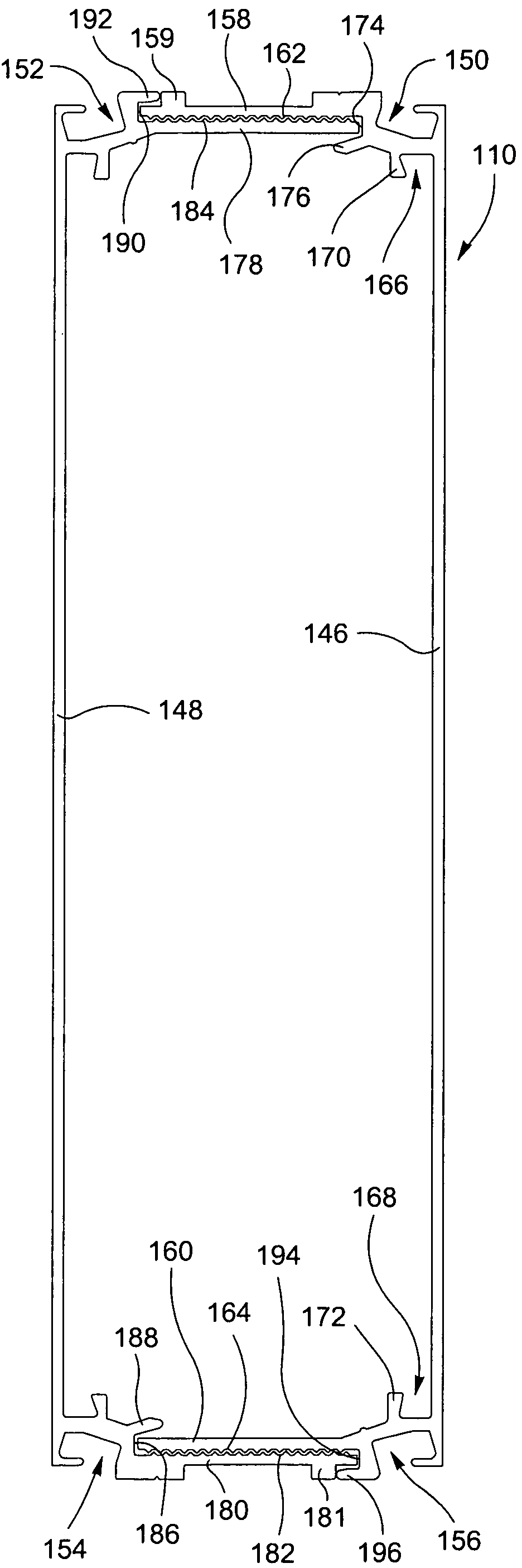
[0019]In the illustrated embodiments, each half beam section identically corresponds in shape and configuration to the beam half section with which it is engaged, overlapped, and locked. For ease of description, however, the respective beam half sections are assigned respective independent reference numerals as are the legs or flanges thereof.

[0020]In example embodiments of the invention, an extra restraint is provided in the form of a lip for receiving and engaging the free end of the exteriorly disposed flange of each of beam half section so that both the inner flange and outer flange of each beam half section abuts and is seated by a respective lip.

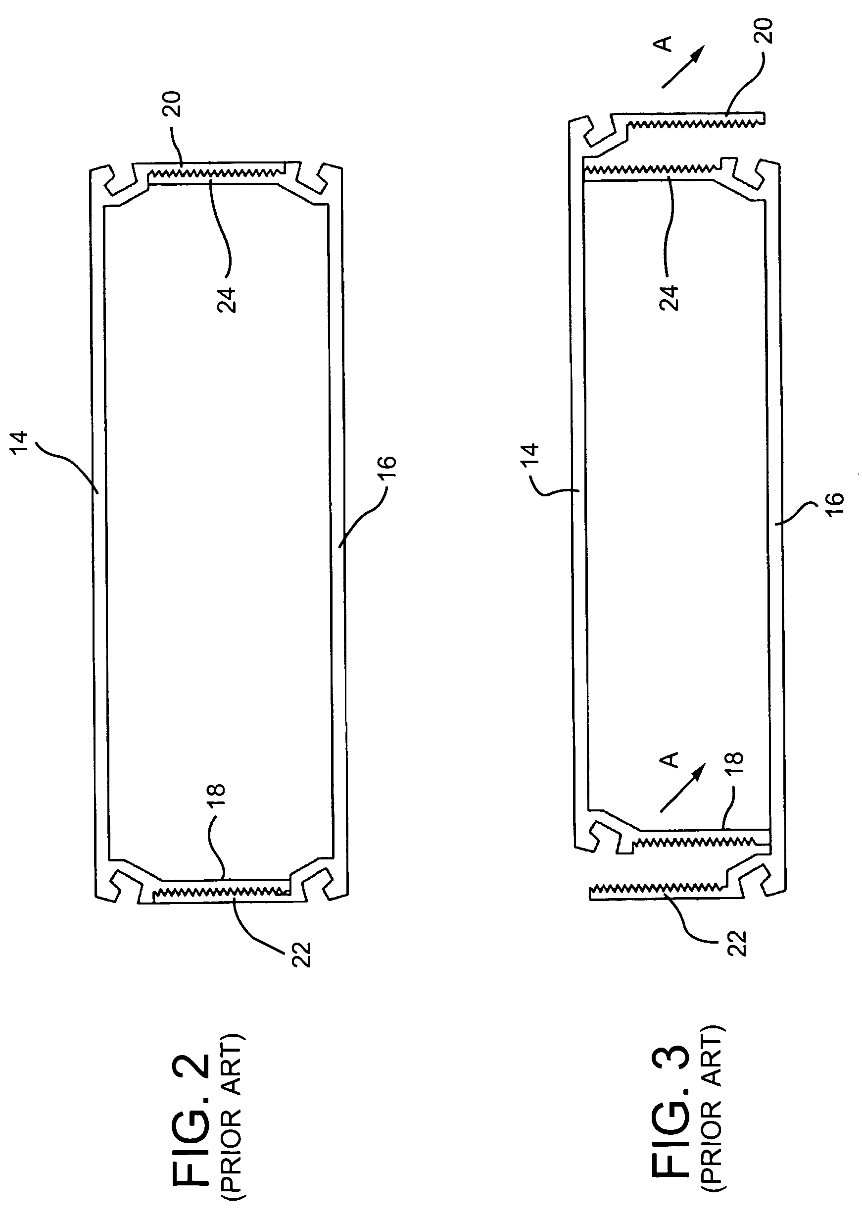
[0021]A first example embodiment of a beam assembly for a screened patio or pool enclosure is illustrated in FIG. 5. More specifically, in this embodiment the beam assembly includes two beam half sections 46,48. On the exterior of beam half sections 46,48 are grooves 50,52,54,56 for receiving spline that is used with screening of enclo...


PUM


Abstract

Two U-shaped beam half sections are attached together by having nesting ledges / receptacles on the flanges of the half sections. While the flanges of each beam half overlap against each other, the nesting ledges / receptacles hold the beam half flanges to fixed locations. Fasteners such as screws can be driven through the sides of the beam half flanges to fixedly lock the beam half sections to one another.

Description

BACKGROUND OF THE INVENTION[0001]The present invention relates to a beam configuration for use in a frame of a screened enclosure, such as a patio or pool screen enclosure.[0002]FIG. 1 is a perspective view of a basic screened enclosure 11 attached to another structure such as a house 12.[0003]Most pool screen and screened enclosure applications use individual metal beams that must be assembled together. Each beam is comprised of half sections that are fitted to one another and then screwed or riveted.[0004]FIG. 2 is a side cross-sectional view of two beam half sections 14,16 of a first prior art beam assembly. A common problem with the illustrated structure is keeping and supporting the beam half sections in the configuration shown in FIG. 2. For example, if beam half section 14 is positioned on top of beam half section 16, the legs or flanges 18,20 of upper beam half section 14 can fall in the direction of arrow A (FIG. 3) and no longer be adjacent the legs or flanges 22,24 of hal...

Claims


Application Information

Patent Timeline
Patent Type & Authority Patents(United States)
IPC IPC(8): E04C3/00
CPCE04C3/06E04C2003/0465E04C2003/043E04C2003/0413
Inventor SHELTON, WILLIAM B.CROSTIC, JR., WILLIAM H.
Owner THE HONG KONG UNIV OF SCI & TECH
Why Eureka
Try Eureka