Drive control apparatus for forklift

a control apparatus and forklift technology, applied in the direction of tractors, pedestrian/occupant safety arrangements, vehicular safety arrangements, etc., can solve the problems of inability to ensure the driving stability of the forklift, the change of the contents of the limitation is not taken into account, and the forklift is unstable. achieve the effect of ensuring the driving stability of the vehicl

Active Publication Date: 2009-08-04
TOYOTA IND CORP
View PDF24 Cites 38 Cited by
  • Summary
  • Abstract
  • Description
  • Claims
  • Application Information

AI Technical Summary

Benefits of technology

[0005]Accordingly, it is an objective of the present invention to provide a drive control apparatus for a forklift that suppresses sudden acceleration and deceleration accompanying a change in the contents of limitation on the driving of the vehicle, thereby ensuring the driving stability of the vehicle.

Problems solved by technology

Driving of a forklift can be unstable during acceleration or deceleration.
However, according to Japanese Laid-Open Patent Publication Nos. 2001-31391 and 2001-163597, in which the driving of a forklift is limited, changes in the contents of limitation are not taken into consideration.
That is, no control procedure is executed for ensuring the driving stability at such changes.
Therefore, in a forklift the driving of which is limited, the contents of limitation are changed when the load state is changed during driving.
Such a sudden change in the vehicle speed can result in an unstable driving.

Method used


Image

  • Drive control apparatus for forklift
  • Drive control apparatus for forklift
  • Drive control apparatus for forklift

Examples


first embodiment

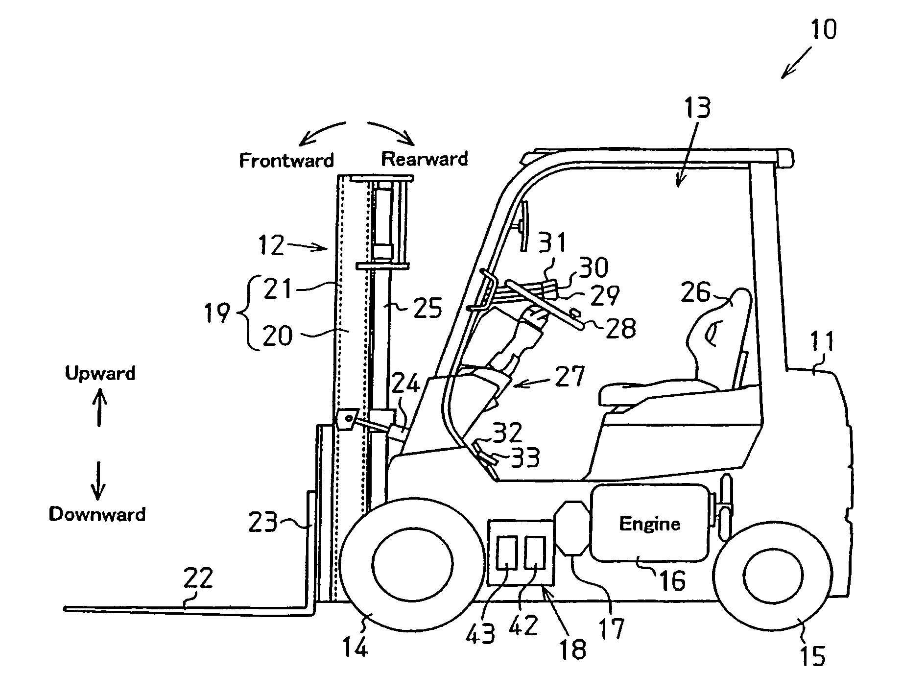
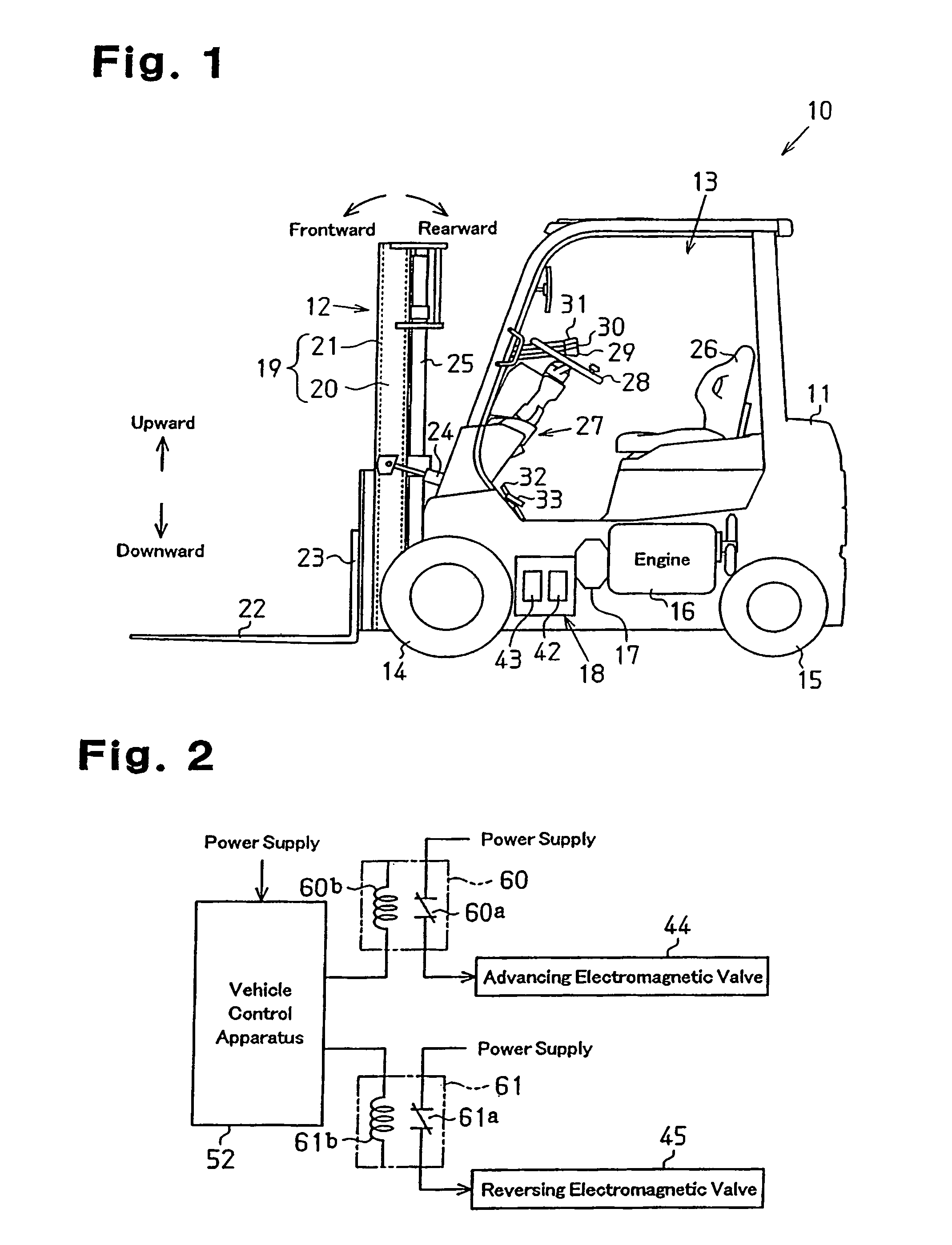
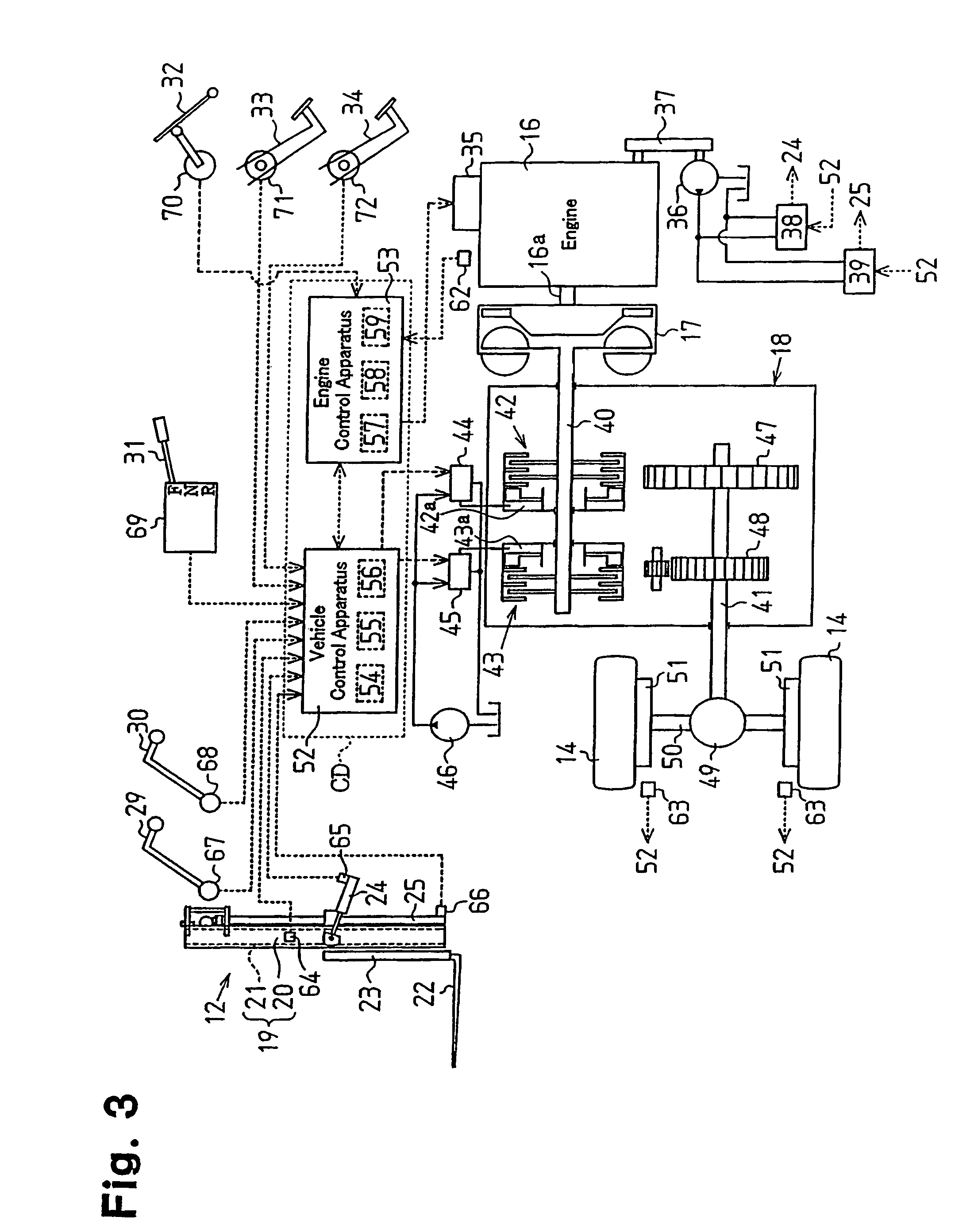
[0026]A drive control apparatus CD for use in a forklift 10 according to a first embodiment of the present invention will now be described with reference to FIGS. 1 to 9.

[0027]FIG. 1 is a side view of the forklift 10. As shown in FIG. 1, the forklift 10 includes a loading device 12 at a front portion of a vehicle body 11. A cab 13 is formed in a center portion of the vehicle body 11. Drive wheels (front wheels) 14 are located in front and lower portions of the vehicle body 11, and steered wheels 15 are provided in rear and lower portions of the vehicle body 11. The vehicle body 11 also mounts a transmission 18 having a torque converter 17. The transmission 18 forms a power transmission mechanism. An engine 16 is coupled to the drive wheels 14 by way of the transmission 18 having the torque converter 17. The transmission 18 is located between the drive wheels 14 and the engine 16. The forklift 10 of this embodiment is an engine type (engine vehicle), in which the drive wheels 14 are ...

second embodiment

[0080]A second embodiment of the present invention will now be described. In the following embodiments, explanations of the same components of the already described embodiment will be omitted or simplified.

[0081]FIG. 10 illustrates the configuration of a forklift 10 according to the present embodiment. As shown in FIG. 10, a wheel angle sensor 81 is provided at one end of an axle 80 of the steered wheels 15. The wheel angle sensor 81 detects a wheel angle that indicates the steered angle of the steered wheels 15. In the present embodiment, the wheel angle sensor 81 is, for example, a potentiometer. The wheel angle sensor 81 is connected to the vehicle control apparatus 52 and outputs a detection signal (wheel angle signal) corresponding to the wheel angle.

[0082]In the forklift 10 of the present embodiment, when the load state is in a region corresponding to the fork height equal to or higher than the height H and the load weight less than the weight W in the necessity determining da...

third embodiment

[0090]A third embodiment of the present invention will now be described. This embodiment may be applied to the first and second embodiments.

[0091]In this embodiment, load fluctuation generated during driving of the forklift 10 is monitored, and a control procedure for changing the contents of limitation on the driving in accordance with the load fluctuation is executed. The load fluctuation in the present embodiment refers to the weight of the load mounted on the loading device 12 (the forks 22). When the forklift 10 is moving, the accompanying vibration causes a load to vibrate, and the value of a detection signal outputted by the load sensor 66 is less stable than the case where the forklift 10 is not moving. Therefore, in the limitation determining process shown in FIG. 7, the contents of limitation is likely to be repeatedly changed during driving by the influence of the detection signal indicating the load weight obtained at step S10 (influence of load fluctuation). Referring t...


PUM


Abstract

A drive control apparatus for a forklift. Based on the load state, it is determined whether to limit a maximum vehicle speed and an acceleration / deceleration during traveling of the forklift. Limitation contents regarding the maximum vehicle speed and the acceleration / deceleration is determined based on a determination result of whether to put the limitations. A speed of the engine is adjusted based on the determined limitation contents, thereby controlling driving of the forklift. When the determined limitation contents are changed, an acceleration / deceleration limitation value is selected from a plurality of acceleration / deceleration limitation values according to the pattern of the change of the limitation contents, and drive control related to the acceleration / deceleration is executed to limit the acceleration / deceleration of the forklift by using the selected acceleration / deceleration limitation value.

Description

BACKGROUND OF THE INVENTION[0001]The present invention relates to a drive control apparatus for controlling driving of a forklift.[0002]Conventionally, forklifts are widely used as industrial vehicles for handling loads (picking up and placing of loads) in plants. Due to its characteristic usage, the driving stability of this type of forklift greatly varies depending on the load state. For example, the center of gravity of the vehicle is shifted and the driving stability varies between a state of carrying no loads and a state of carrying a load. When carrying a load, the driving stability varies depending on the weight of the load, the height of the fork on which the load is mounted, the tilt angle of the fork. Thus, conventionally, techniques for limiting the driving of a forklift to improve the driving stability of the vehicle have been disclosed in Japanese Laid-Open Patent Publication Nos. 2001-31391 and 2001-163597. The technique disclosed in the publication No. 2001-31391 limi...

Claims


Application Information

Patent Timeline
Patent Type & Authority Patents(United States)
IPC IPC(8): B60K28/08B66F17/00
CPCB66F17/003B66F9/07572B60Y2200/15
Inventor YAMADA, TADASHIOKA, HIDENORIKAMIYA, TOSHIKAZUHASEGAWA, KIMIHIDEMIURA, MICHIHIROTAKAHASHI, MASAYUKIKOBAYASHI, HIROKAZU
Owner TOYOTA IND CORP
Why Eureka
Try Eureka