Cup holder unit providing stability for holding member

a technology for holding members and cups, which is applied in the direction of washing tables, chairs, machine supports, etc., can solve the problems of reducing the switching operation performance and the lack of design flexibility of the unit, and achieve the effects of improving design flexibility, compactness, and reducing the overall size of the tray

Inactive Publication Date: 2009-08-04
NIFCO INC +2
View PDF59 Cites 27 Cited by
  • Summary
  • Abstract
  • Description
  • Claims
  • Application Information

AI Technical Summary

Benefits of technology

[0016]The present invention described above has the following effects. In a first aspect, the tray and the holder member are moved relatively and in accordance with the movements of the shafts corresponding to the clearance slots, i.e., the vertical and arc-shaped slots, thereby improving design flexibility. The resulting effects include, for example, a more compact unit achieved by reducing an overall size of the tray without diminishing the holding performance and appearance, improved holding performance achieved by enabling the holder member to rise substantially horizontal to the tray, and simplification achieved by omitting the spring member for raising the holder member that is essential in the conventional unit.
[0017]In a second aspect, the slot forming sections, which define the arc-shaped slots, are disposed so as to enable resilient displacement, and the shafts are slid while they resiliently abut against the slot forming sections. Subsequent to the rise of the holder member effected by the shafts in connection with the vertical slots of the clearance slots and the guide grooves, rattling of the holder member is absorbed when and after it is further moved forward relative to the tray by the shafts that move into the arc-shaped slots of the clearance slots, thereby improving operation characteristic.

Problems solved by technology

Since the holder member 52 is raised by pivoting about the pin 53 using the bias force of the spring member, the bias force of the spring member needs to be large, which becomes a factor in reducing the switching operation performance.
Thus, the unit lacks design flexibility.

Method used


Image

  • Cup holder unit providing stability for holding member
  • Cup holder unit providing stability for holding member
  • Cup holder unit providing stability for holding member

Examples


Embodiment Construction

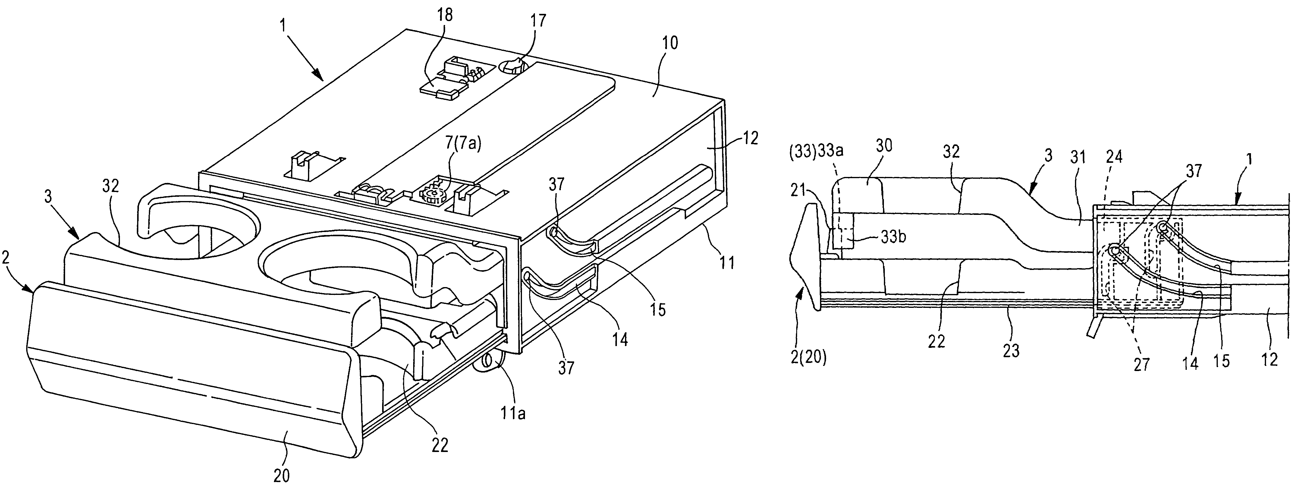
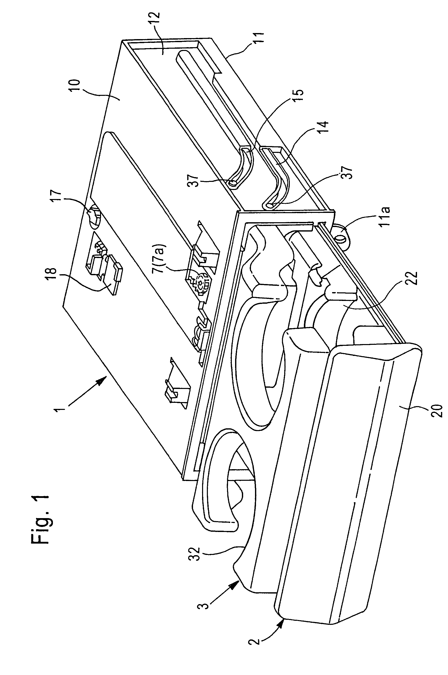
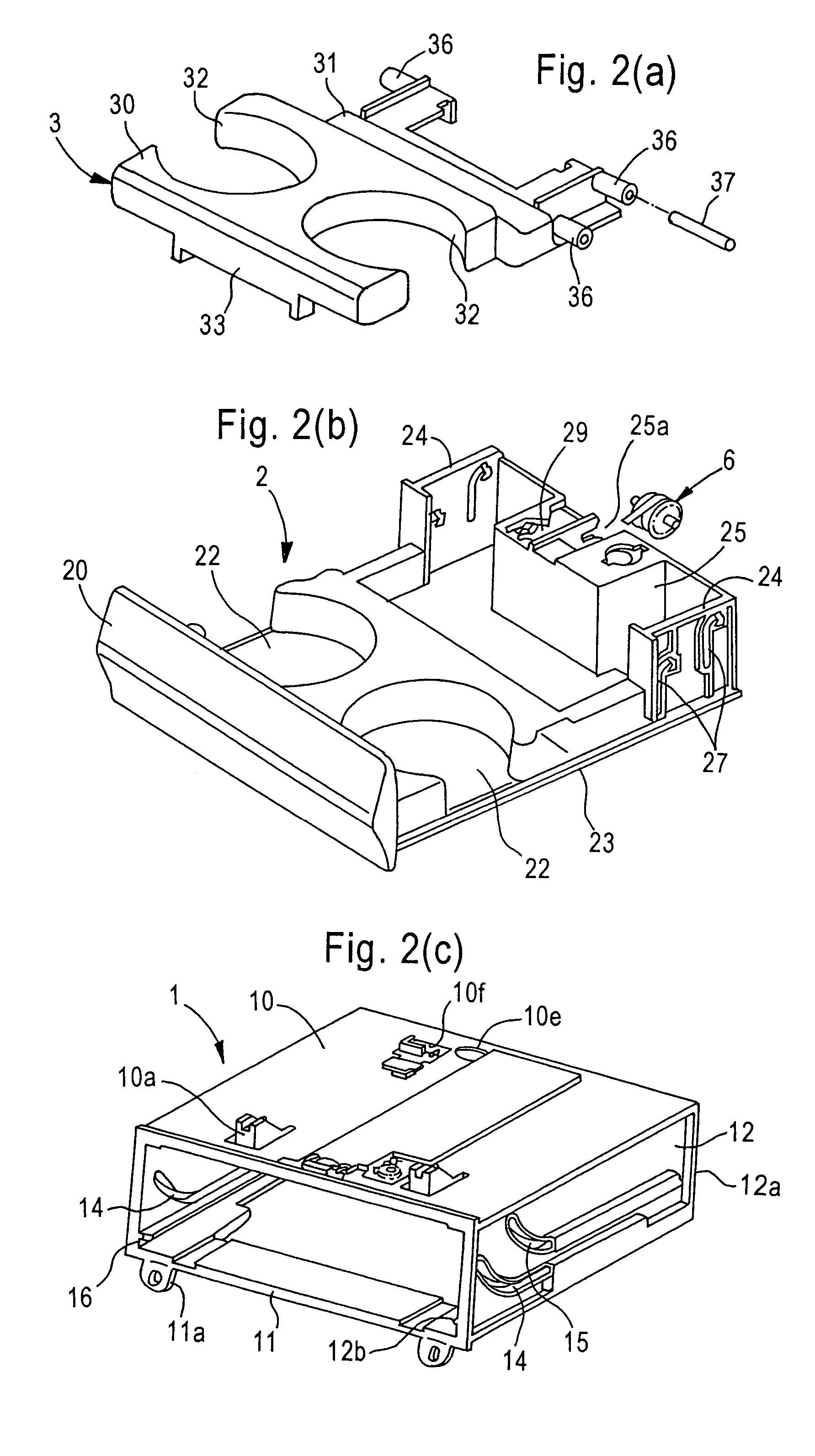
[0028]Hereunder, embodiments of the present invention will be explained with reference to the accompanying drawings. FIGS. 1 and 2(a) to 2(c) are views of the cup holder unit. FIGS. 3(a) to 3(c) show a case unit, wherein FIG. 3(a) is a top view thereof, FIG. 3(b) is a side view thereof, and FIG. 3(c) is a sectional view taken along line 3(c)-3(c) in FIG. 3(a). FIGS. 4(a) to 4(c) show a tray unit, wherein FIG. 4(a) is a top view thereof, FIG. 4(b) is a side view thereof, and FIG. 4(c) is a sectional view taken along line 4(c)-4(c) in FIG. 4(a). FIGS. 5(a) and 5(b) show a holder member unit, wherein FIG. 5(a) is a top view thereof and FIG. 5(b) is a side view thereof. FIG. 6 is a schematic showing a relationship between a support rib and an abutting rib. FIGS. 7(a) and 7(b) show an operation of the unit, and FIGS. 8(a) and 8(b) also show the operation. In the following description, a detailed explanation of the unit construction will be followed by a description of the operation.

(Unit...


PUM


Abstract

A cup holder unit includes a housing case; a rest tray that switches between a pulled out position where it is moved forward from the case and a stored position where it is pushed in the case; and a holder member switchable from a non-usable position where it is superposed above the tray and stored in the case to a usable position where it is raised by a forward movement of the tray. The cup holder unit has shafts projecting from the holder member to be spaced apart from each other; clearance slots disposed in upright walls of the tray; and guide grooves disposed in the case and slanted upwardly toward front to slidably receive the shafts therein via the clearance slots. Each clearance slot includes a vertical slot and an arc-shaped slot turning toward a rear side from an upper section of the vertical slot.

Description

BACKGROUND OF THE INVENTION AND RELATED ART STATEMENT[0001]The present invention relates to a cup holder unit for holding a can, container, or the like, wherein the cup holder unit can stably hold a holder member.[0002]FIG. 9 shows a cup holder unit disclosed in Patent Reference 1, which comprises a housing case (retainer) 50, a tray 51 that switches between a pulled-out position and a stored position relative to the case 50, and a holder member 52 that switches from a non-usable position where it is superposed above the tray 51 and housed in the case 50 to a usable position where it is raised by a forward movement of the tray 51. When the holder member 52 is in the usable position, a container K, rested on the tray 51, is surrounded and restricted by a hole of a holding section 52a. The tray 51 has a pair of mounting pieces 51a projecting from a bottom surface thereof, and is moved along guide rails disposed at both inner sides of the case 50.[0003]The holder member 52 has a pair o...

Claims


Application Information

Patent Timeline
Patent Type & Authority Patents(United States)
IPC IPC(8): B60N3/00B60R7/00B60R7/06
CPCB60N3/102Y10S224/926
Inventor KOGAMI, MITSURUHANANO, MASAKAZUTOBA, EIJI
Owner NIFCO INC
Why Eureka
Try Eureka