Osteosynthetic aid

a technology of osteosynthesis and nail shank, which is applied in the direction of osteosynthesis devices, prosthesis, screws, etc., can solve the problems of not being able to secure the location of the nail shank, the locking screw to come unscrewed,

Active Publication Date: 2009-08-04
STRYKER EURO OPERATIONS HLDG LLC
View PDF18 Cites 20 Cited by
  • Summary
  • Abstract
  • Description
  • Claims
  • Application Information

AI Technical Summary

Benefits of technology

[0004]It is the object of the invention to provide an osteosynthetic aid which ensures that the ten...

Problems solved by technology

A peculiar problem in using locking nails of this type, e.g. for humeral head fractures, is posed by the postsurgical migration of the screws.
Since the bone fragments may move or the bone is resorbed the bias which is produced while the locking nail is screwed in can be lost and, as a resu...

Method used


Image

  • Osteosynthetic aid
  • Osteosynthetic aid
  • Osteosynthetic aid

Examples


Embodiment Construction

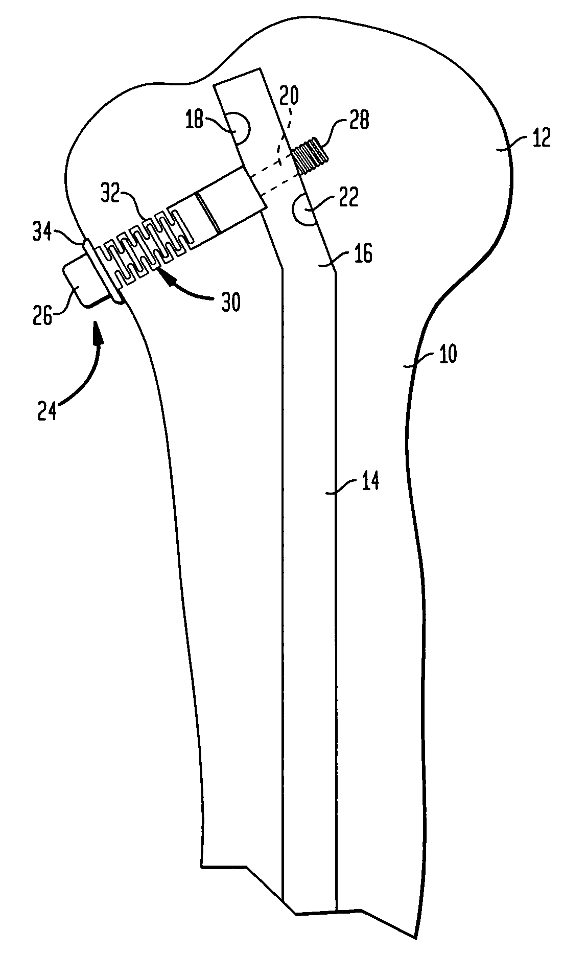
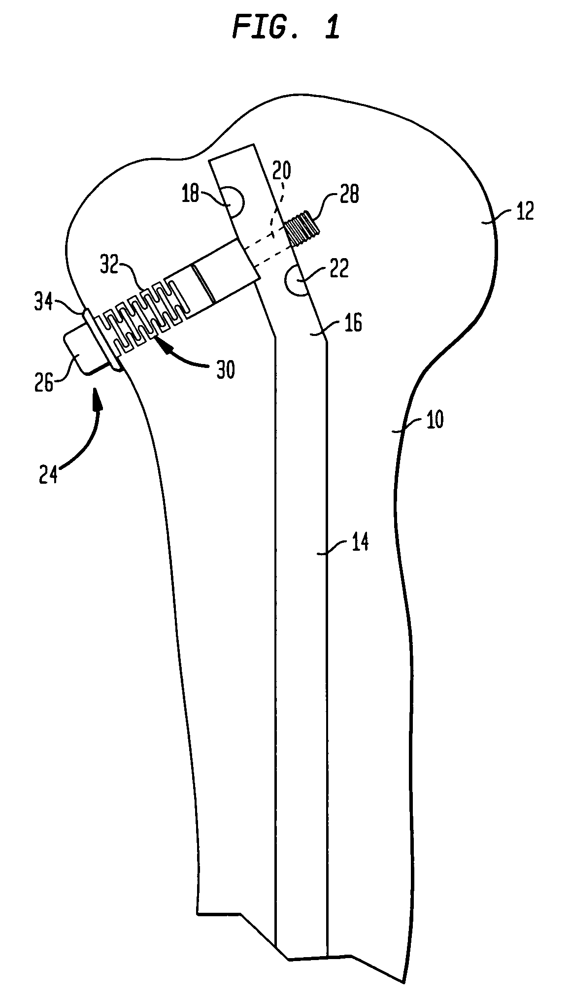
[0016]Referring to FIG. 1, there is shown the proximal portion of a humerus generally denoted as 10. The humeral head is denoted as 12. A locking nail 14 of a conventional structure is introduced through head 12. In the preferred embodiment, it is curved or bent at 16. In the preferred embodiment, the proximal portion has three cross-bores 18, 20 and 22 which are angularly offset and are located at an axial distance from each other. Preferably, they are provided with a thread (not shown).

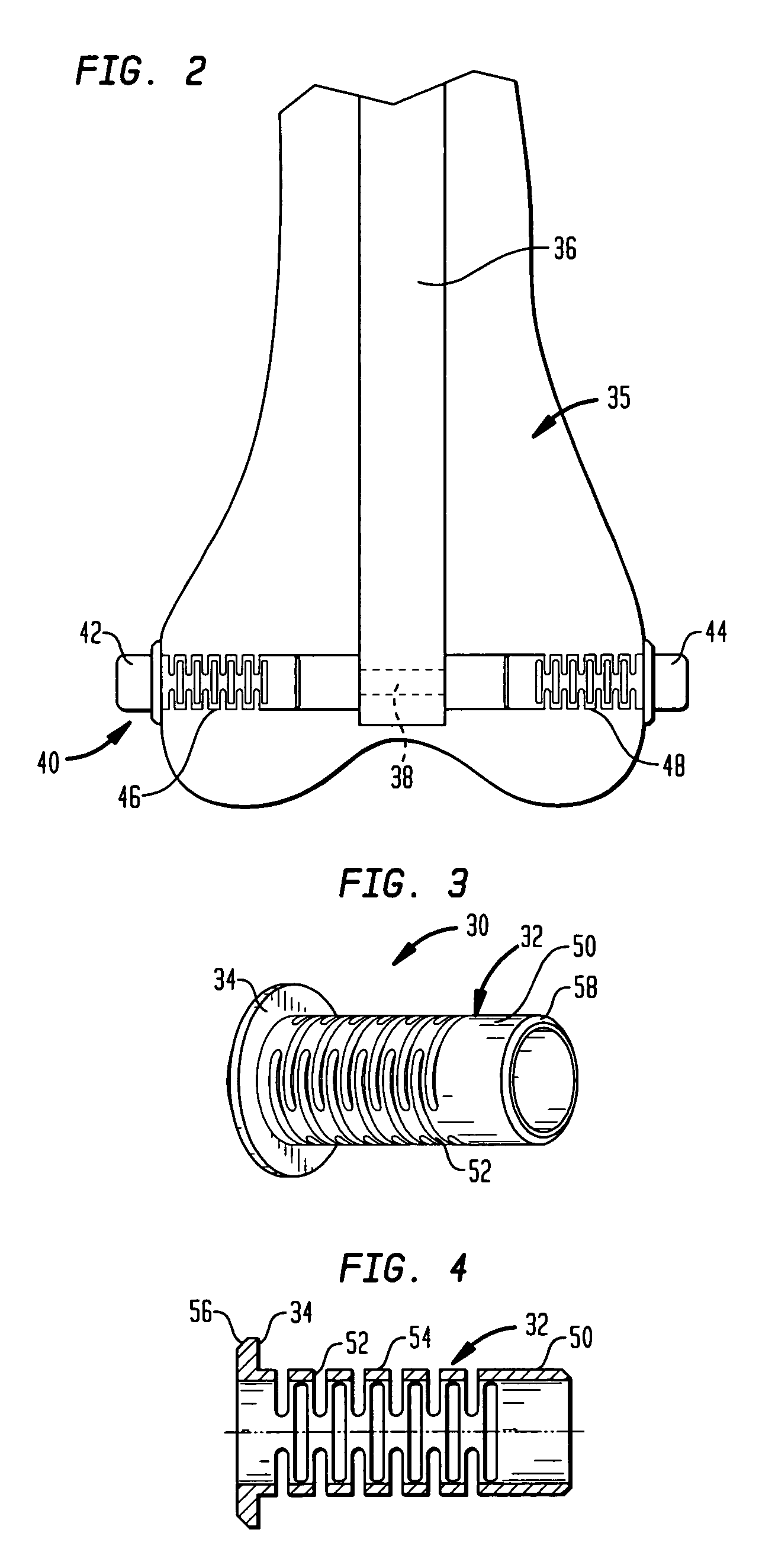
[0017]The cross-bores 18 to 22 serve for the reception of a locking screw one of which is shown at 24. Screw 24 has a head 26 and a shank 28 which has a threaded portion. The threaded portion is seated in the thread of cross-bore 20. Arranged on the shank 28 of locking screw 24 is a sleeve 30 which has a shank 32 positioned in an axial direction, and a radially circumferential flange 34 at one end.

[0018]During a surgery, the corticalis of the humerus 10 is bored open to such an extent that the biasi...


PUM


Abstract

An osteosynthetic aid for tubular bones includes a locking nail which has a shank and, at the two ends of said shank, has at least one cross-bore for a headed locking screw. A biasing sleeve is resiliently deformable in an axial direction and is disposed between the head of the locking screw and the shank of the locking nail. The sleeve maintains the cross-locking screw under tension to keep the shank of the nail from shifting during use.

Description

BACKGROUND OF THE INVENTION[0001]The invention relates to an osteosynthetic aid for tubular bones. More specifically, the invention relates to a locking nail system as has become known for the fixation of fractures of tubular bones, particularly the femur, tibia or humerus. The basic principle is embodied in an elongate nail shank which has at least one cross-bore at each of its ends. The cross-bore is traversed by a bone screw or locking screw with which the nail shank is located in the bone in both the axial and rotational directions.[0002]A peculiar problem in using locking nails of this type, e.g. for humeral head fractures, is posed by the postsurgical migration of the screws. Since the bone fragments may move or the bone is resorbed the bias which is produced while the locking nail is screwed in can be lost and, as a result, can cause the locking screw to come unscrewed.[0003]When the locking nail is employed as a supracondylar nail it is known to pass a so-called tibial bolt ...

Claims


Application Information

Patent Timeline
IPC IPC(8): A61B17/56A61B17/58A61F2/30A61B17/68A61B17/72A61B17/74A61B17/86
CPCA61B17/725F16B31/04A61B17/8685A61B17/72A61B17/864A61B17/869A61B2017/8655
Inventor ZANDER, NILSCREMER, AXELSEEMANN, MICHAEL
Owner STRYKER EURO OPERATIONS HLDG LLC
Why Eureka
Try Eureka