

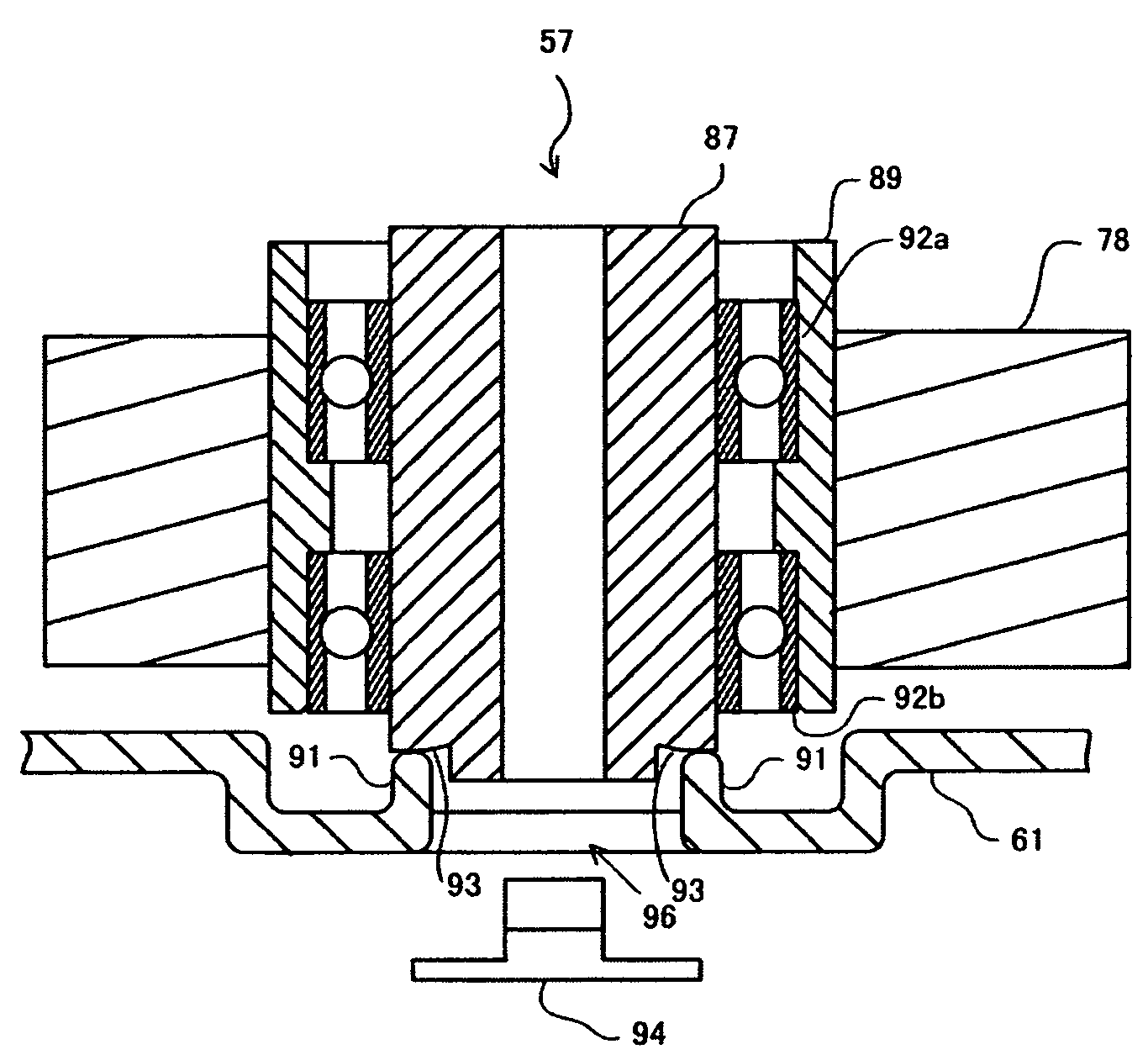
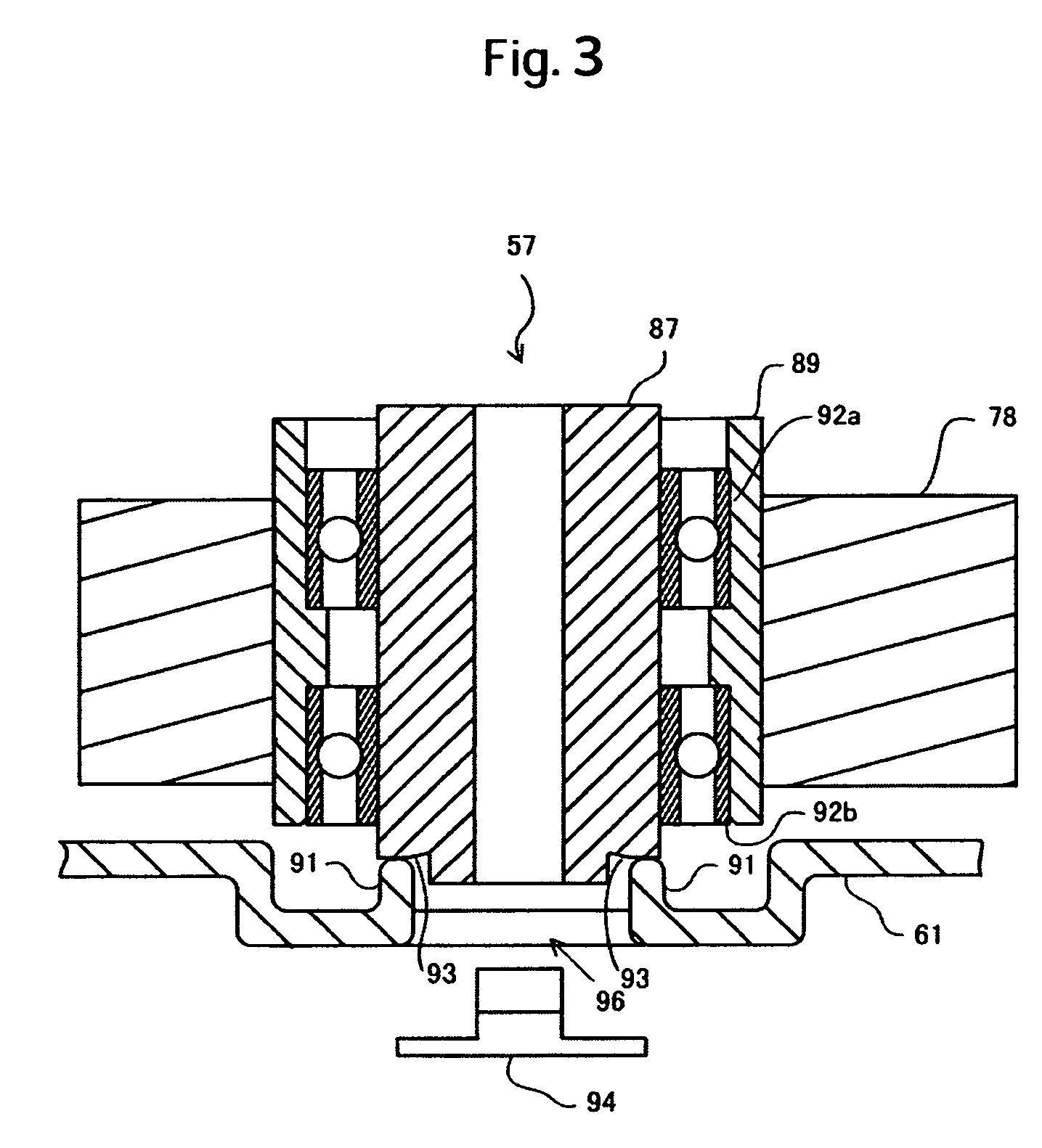
Boss location to adjust head attitude
a head position and head technology, applied in the direction of mechanical equipment, record information storage, instruments, etc., can solve the problems of inability to satisfactorily cope with the conventional structure of the pivot receiving surface, degrade the flying performance, etc., and achieve the effect of stable flying height, easy adjustment, and easy adjustmen
- Summary
- Abstract
- Description
- Claims
- Application Information
AI Technical Summary
Benefits of technology
Problems solved by technology
Method used
Image

Examples
Embodiment Construction
[0029]One embodiment of a pivot receiving surface in a magnetic disk drive is shown in FIG. 8, in which a boss 5 having three projections 3a, 3b and 3c formed thereon is disposed at the bottom of a base, and further, a pivot receiving surface constituted of the three projections is designed to support an abutment surface formed at the bottom of a pivot assembly. In this case, the three projections are arranged such that the first projection 3a is formed in such a manner that the center of the first projection 3a is located on a line 11 connecting a rotation center 9 of a carriage assembly, which is referred to also as the center of the pivot assembly, and a rotational center 7 of a magnetic disk 1 to each other, and that the second projection 3b and the third projection 3c are formed at an equiangular interval of 120° on the rotation center 9.
[0030]The above-described arrangement is convenient for determining mainly the positions of the projections 3a, 3b and 3c in reference to the ...
PUM
| Property | Measurement | Unit |
|---|---|---|
| angle | aaaaa | aaaaa |
| angles | aaaaa | aaaaa |
| angle | aaaaa | aaaaa |
Abstract
Description
Claims
Application Information