
Head slider and disk drive apparatus

Inactive Publication Date: 2006-02-14
PANASONIC CORP
View PDF8 Cites 0 Cited by
  • Summary
  • Abstract
  • Description
  • Claims
  • Application Information

AI Technical Summary

Benefits of technology

[0010]It is an object of the present invention to provide a head slider structure capable of maintaining a stable flying height above a disk surface even if the relative speed between the head slider and the disk is lowered and hardly avoiding significant damage to the head slider or the disk even if the head slider is subjected to an external shock, and also to provide a disk drive using such a head slider.
[0018]By virtue of such a structure, the head slider is able to maintain a flying height at a substantially satisfactory level even when the disk rotates at a low speed and the relative speed between the head slider and the disk is lowered. Also, such an advantageous effect can be obtained that variations of the flying height can be suppressed even if the head slider is subjected to changes in the relative speed or changes in the atmospheric pressure. Further, the head slider can be provided with good shock resistance such that the head slider and the disk are hardly damaged even when the head slider is subjected to an external shock force. Accordingly, a disk drive is provided which is small, thin, and consumes little power and is thus mountable on portable equipment.

Problems solved by technology

In order to realize a still smaller disk drive and to have it mounted on portable equipment represented by mobile telephones, there also arises a very important problem of reducing the power consumption.
More specifically, though smaller diameter disks are required in order for disk drives to be mounted on portable equipment, it is a problem to increase the number of revolutions because doing so incurs an increase in power consumption.

Method used


Image

  • Head slider and disk drive apparatus
  • Head slider and disk drive apparatus
  • Head slider and disk drive apparatus

Examples


first exemplary embodiment

(First Exemplary Embodiment)

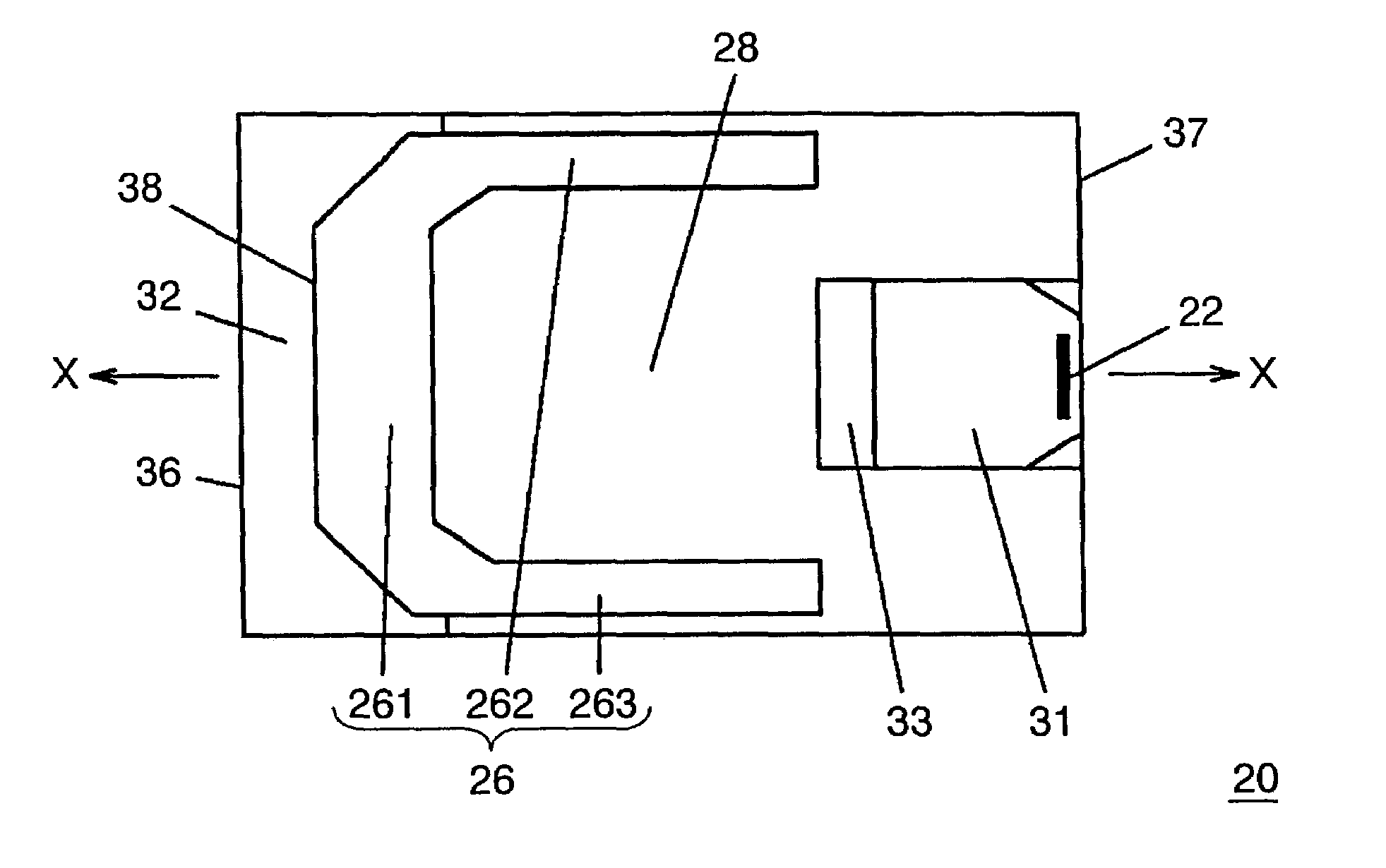
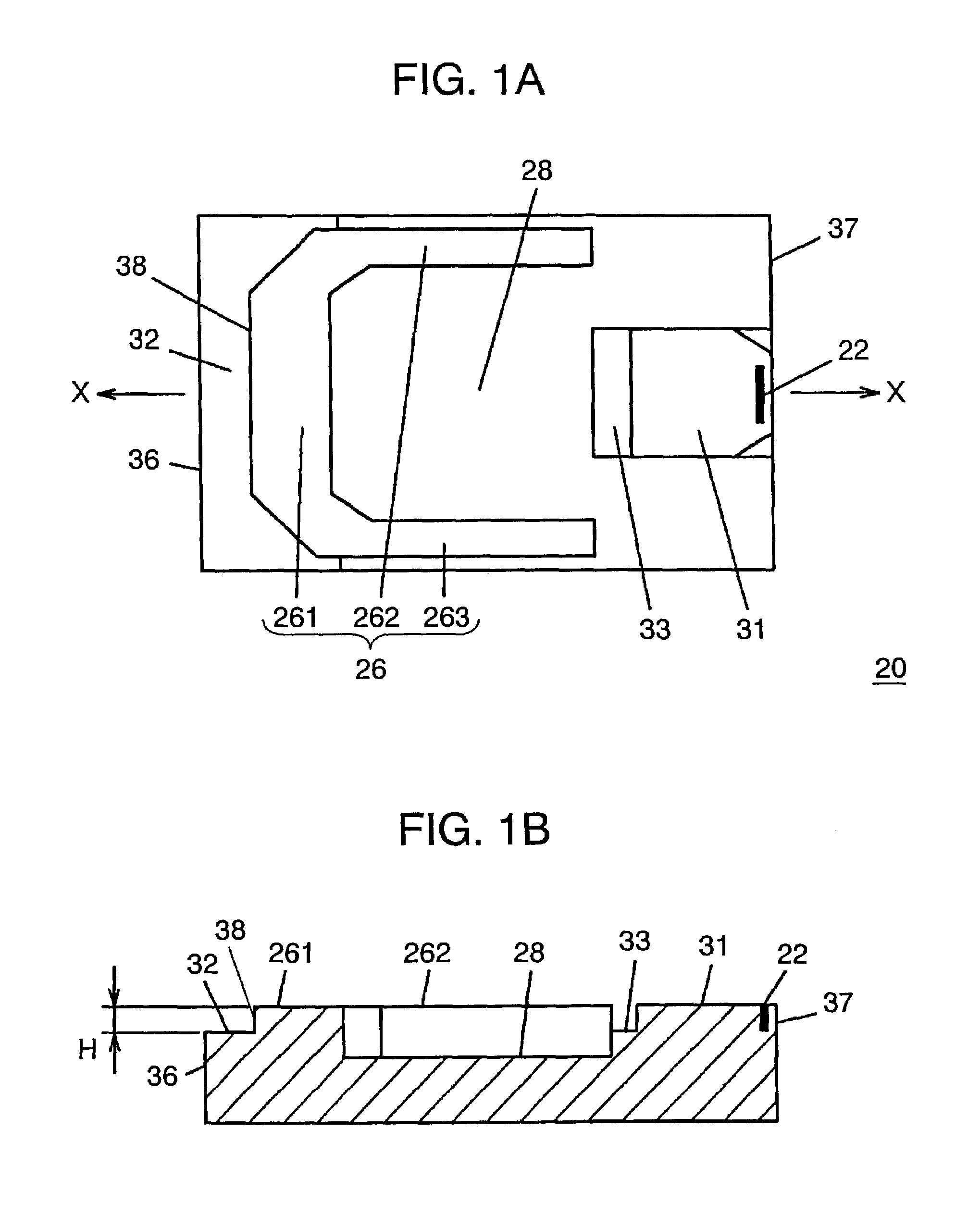
[0038]FIG. 1A is a plan view of a head slider 20 of a first embodiment of the present invention showing its disk-facing surface, and FIG. 1B is a sectional view taken along the line X—X of FIG. 1A. Head slider 20 is formed in a substantially rectangular parallelepiped shape, which has an upstream edge portion 36 on a forward side and a downstream edge portion 37 on a rearward side, with respect to the rotating direction of a disk. In the present embodiment, the disk-facing surface is configured to have a first positive-pressure generating section 26, a second positive-pressure generating section 31, a negative pressure generating section 28, an upstream-side intermediate-level portion (surface) 32, a downstream-side intermediate-level portion 33, and a head 22 disposed on the second positive-pressure generating section 31.

[0039]The configuration will be described below in more detail. At a position a predetermined distance apart from upstream edge portion...

second exemplary embodiment

(Second Exemplary Embodiment)

[0057]FIG. 8A is a plan view of a head slider 203 of a second embodiment of the invention showing its disk-facing surface, and FIG. 8B is a sectional view taken along the line Y—Y of FIG. 8A. Components corresponding to those shown in FIG. 1A and FIG. 1B are denoted by like reference numerals. In the present embodiment, there is provided a projected portion 150 on the upstream-side intermediate-level portion (surface) 32. Projected portion 150 is formed to be higher than upstream-side intermediate-level portion 32. Cross rail 261 is formed to be lower than projected portion 150 and higher than upstream-side intermediate-level portion 32. Step depth H at stepped portion 38 between cross rail 261 and upstream-side intermediate-level portion 32 is 100 nm or below and, hence, the level difference between upstream-side intermediate-level portion 32 and projected portion 150 is set to be above 100 nm, e.g., it is set to 120 nm. Features other than those descri...

third exemplary embodiment

(Third Exemplary Embodiment)

[0060]FIG. 10A is a plan view of a head slider 205 of a third embodiment of the invention showing its disk-facing surface, and FIG. 10B is a sectional view of the head slider taken along the line Z—Z of FIG. 10A. Components corresponding to those in FIG. 1A and FIG. 1B are denoted by like reference numerals. Head slider 205 of the present embodiment is different from those of the other embodiments in that there is formed a groove 322 in the center along the lateral direction of a cross rail 261 and this groove 322 is joined with upstream-side intermediate-level portion (surface) 32 and is flush with the same. Stability of the flying height and the shock resistance of head slider 205 of the present embodiment when it is attached to the disk drive shown in FIG. 2 are obtained by numerical analysis. Conditions for the analysis are the same as those in the case of the first embodiment and hence explanation thereof will be omitted. By the provision of groove 3...


PUM


Abstract

A Head slider 20 has a substantially rectangular parallelepiped shape and a disk-facing surface adapted to oppose a disk 400, as well as a head 22 disposed on the disk-facing surface for performing record / reproduce operations. The disk-facing surface has a cross rail 261 disposed at a predetermined distance from an upstream edge portion 36 perpendicular to the rotating direction of disk 400, and an upstream-side intermediate-level surface 32 formed to be lower than cross rail 261 and extended from the forward edge of cross rail 261 to upstream edge portion 36. A step depth H at a stepped portion 38 between cross rail 261 and intermediate-level surface 32 is set to be within a range of 5 nm to 100 nm. Thus, a disk drive is provided that is capable of record / reproduce operations while maintaining stable flight of head slider 20 when the relative speed between the head slider and disk is low and that has good shock resistance.

Description

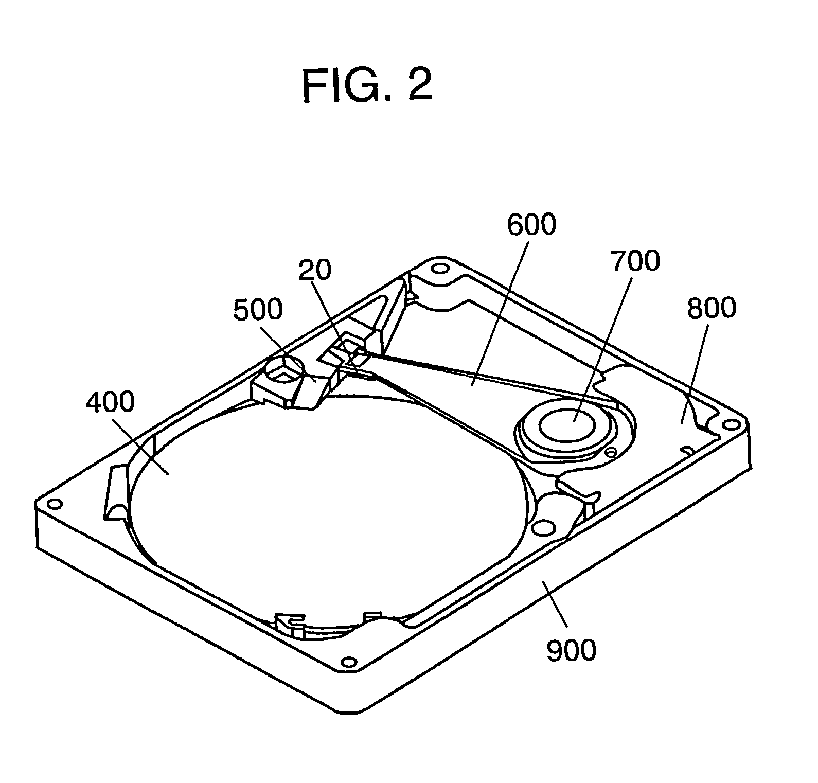
FIELD OF THE INVENTION[0001]The present invention relates to a head slider having mounted thereon a head for recording and / or reproducing data on a disk-shaped recording medium, such as a magnetic disk or a magneto-optic disk, and also relates to a disk drive apparatus using such a head slider.BACKGROUND OF THE INVENTION[0002]Recently, there have been made great technological advances in disk recording / reproducing apparatus (hereinafter referred to as “disk drives”) for recording and / or reproducing data on a disk-shaped recording medium such as a hard disk or an optical disk (hereinafter referred to as “disks”) and their use is expanding not only in conventional computers but also in many other fields. There are increasing demands for such disk drives to have high recording density and, in addition, to be small in size, consume little power, have good shock resistance, and be mountable onto portable equipment.[0003]FIG. 14 is a perspective view schematically showing a disk drive. In...

Claims


Application Information

Patent Timeline
IPC IPC(8): G11B5/60
CPCG11B5/6005G11B5/6082
Inventor UENO, YOSHIHIRODENG, ZHI SHENG
Owner PANASONIC CORP
Learn More