
Slider having a stable flying posture and disk device including the slider

Inactive Publication Date: 2006-06-13
WESTERN DIGITAL TECH INC
View PDF15 Cites 2 Cited by
  • Summary
  • Abstract
  • Description
  • Claims
  • Application Information

AI Technical Summary

Benefits of technology

[0013]According to the present invention, a roll angle of the slider in a region where a skew angle is positive can be controlled so that its variation is equal to or smaller than a desired value and, thus, a stable flying posture of the slider is obtained in the region where the skew angle is positive, thereby securing a stable flying height at a position of minimum flying height.
[0079]According to the present invention, it is possible to provide a very small disk device based on the Compact Flash standard, having high recording density and reliability.

Problems solved by technology

The increase in the data recording capacity promotes size reduction of the magnetic disk devices, and there are being practically used disk devices with high cost effect, such as one disclosed in Japanese Published Patent Application No. Hei. 8-249127, which replace semiconductor memories of various electronic devices such as cameras, facsimiles, portable phones, modems, beepers, hand-held computing equipments, printers, and copy machines.
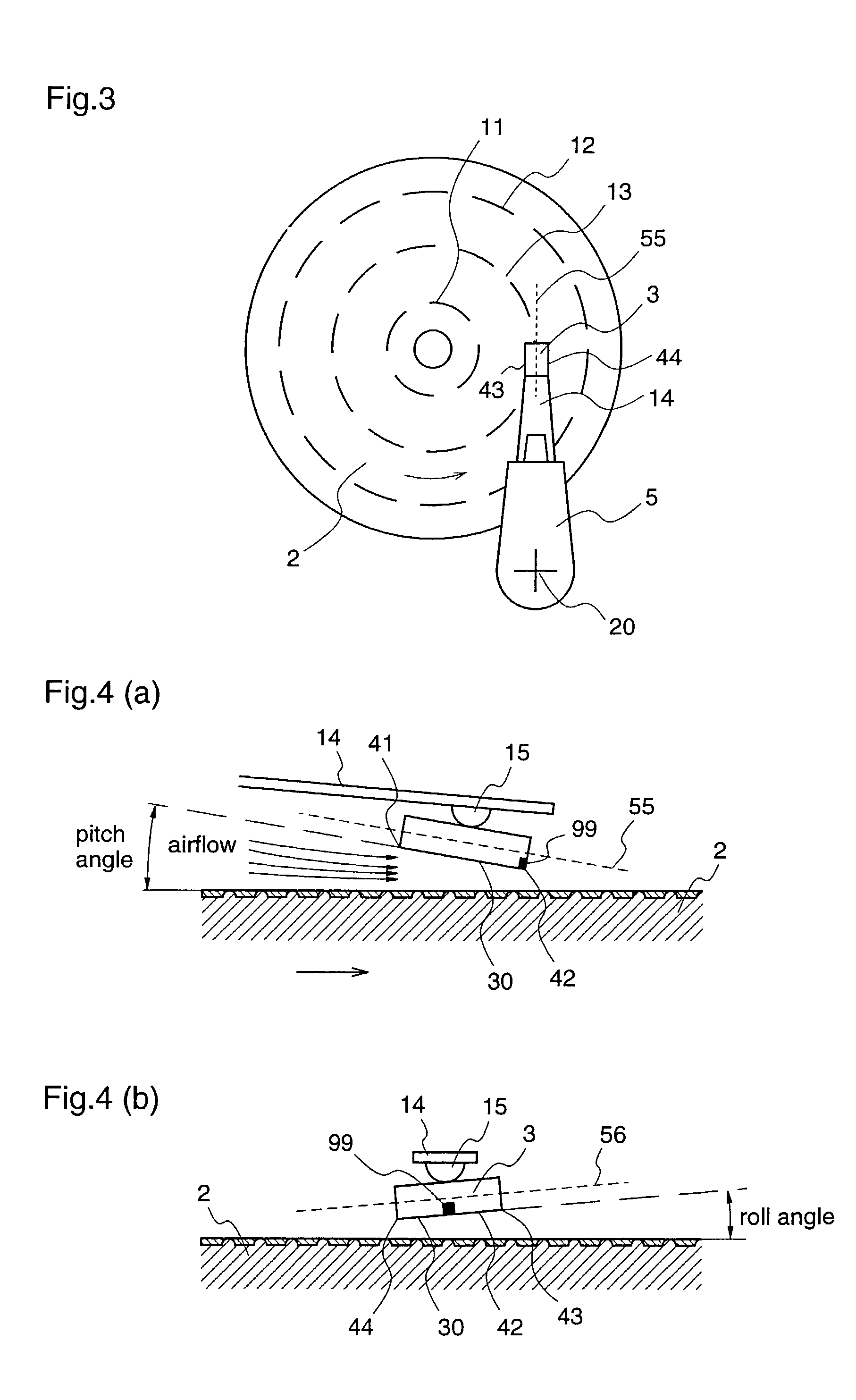
Since the rotation-type actuator is used as described above, directions of movement between the slider and the disk medium and the airflow under the slider are no longer uniform, and they have various angles with respect to the ordinate of the slider (an axis supposed to pass in the center of the slider in the direction of a long side of the slider or the actuator).
Further, when the slider is required to fly at a predetermined height at the above-described magnetic head position, the variation of the slider flying posture, particularly the variation of a roll angle in the direction of the slider abscissa, causes reduction of the flying height at a position of the minimum flying height and, thus, brings the slider and the disk medium into contact, resulting in a risk of inducing so-called head crush.
Thus, sufficient flying force cannot be obtained from airflow and, therefore, it is further difficult to maintain a predetermined flying height and a uniform flying posture.

Method used


Image

  • Slider having a stable flying posture and disk device including the slider
  • Slider having a stable flying posture and disk device including the slider
  • Slider having a stable flying posture and disk device including the slider

Examples


embodiment 1

[0103]Hereinafter, a slider and a disk device according to a first embodiment of the present invention will be described with reference to the drawings.

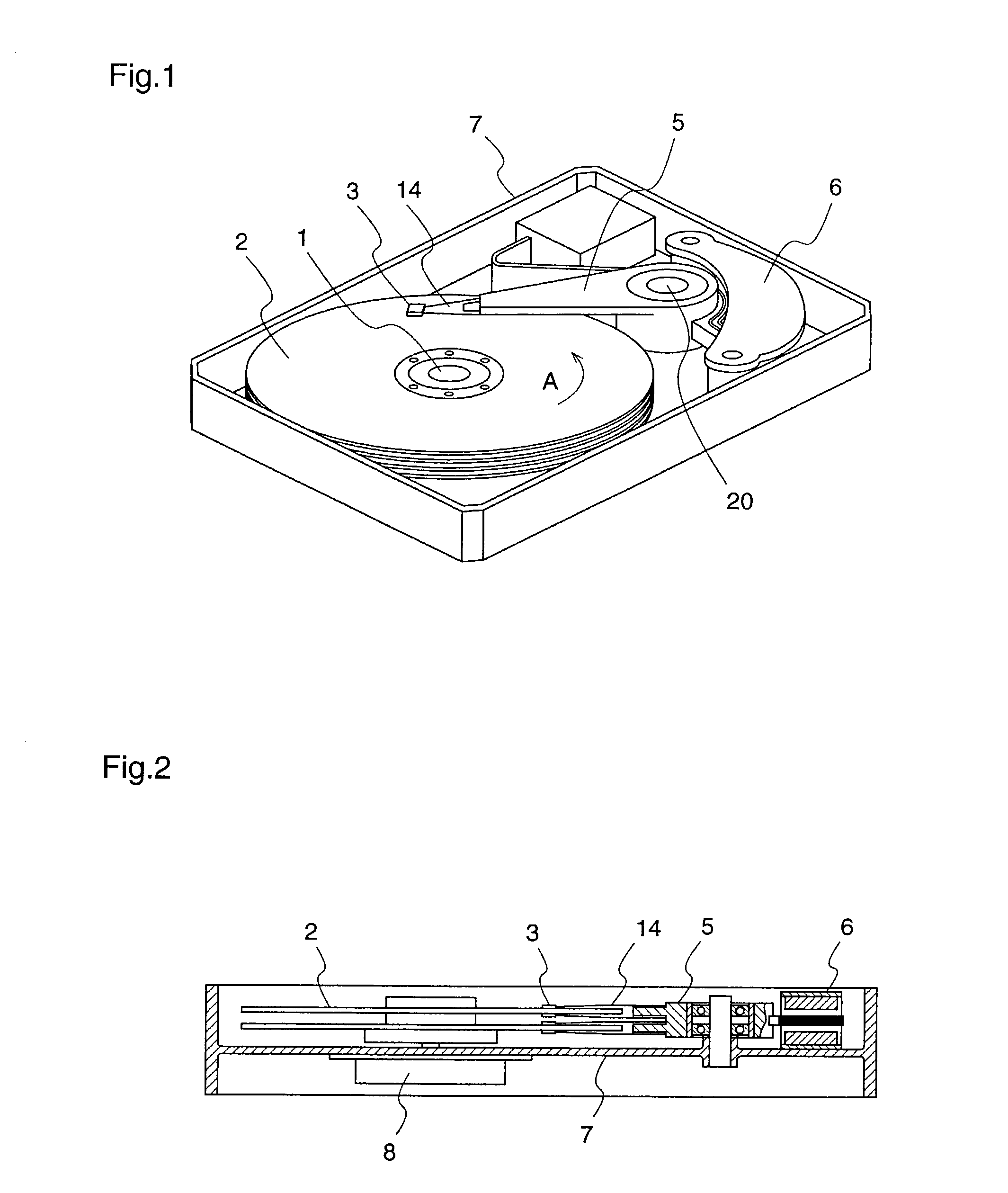
[0104]FIG. 1 is a perspective view illustrating the interior of a magnetic disk device. FIG. 2 is a cross sectional view illustrating the magnetic disk device. The magnetic disk device has a housing cover (not shown), which covers a disk medium 2, a slider 3, and the like. A pair of actuator arms 5, which is attached to an actuator axis 20 so as to be rotated, is rotated about the actuator axis 20 by power of a voice coil motor 6. The suspension 14 is attached to each end of the actuator arm pair 5. A slider 3 having an electromagnetic converter or a magnetic head (not shown in FIG. 1) is attached to each end of the suspension 14.

[0105]A main axis 1 is provided in a housing 7, and a number of disk media 2 are attached to the main axis 1 so as to rotate, with spaces left therebetween. The disk medium 2 rotates with the main axis 1 whi...

embodiment 2

[0130]Hereinafter, a slider and a disk device according to a second embodiment of the present invention will be described with reference to the drawings.

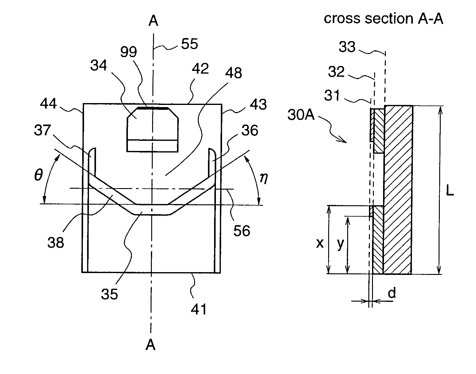
[0131]FIG. 17 is a diagram illustrating flying heights from an ID track 11 to an OD track 12 in cases where a difference in level “d” between the upper surface 31 and the middle surface 32 of the air bearing surface 30A in FIGS. 5(a) and 5(b) is 25 nm, 50 nm, 100 nm, 150 nm, and 200 nm. A mark ● shows the case where the level difference “d” is 25 nm, a mark □ shows the case where the level difference “d” is 50 nm, a mark ▴ shows the case where the level difference “d” is 100 nm, a mark ⋄ shows the case where the level difference “d” is 150 nm, and a mark * shows the case where the level difference “d” is 200 nm. A relative velocity between a slider 3 and the disk medium 2 according to the first embodiment at the MD track 13 of the disk medium 2 with a steady rotational velocity of 4500 rpm is 2π×8.7×(4500 / 60)≈4100 mm / s=4.1 m / s. FIG....


PUM


Abstract

A slider maintains a uniform flying posture and a predetermined flying height by suppressing variations of roll angle and flying height. At an air bearing surface of the slider, an edge line on an air influx end side and an edge line at a disk outer circumference side end are connected by an edge line having a recess angle θ (rad) with respect to an abscissa. The edge line on the air influx end side and an edge line at the disk inner circumference side end are connected by an edge line having a recess angle η (rad) with respect to the abscissa, thereby forming a concave part, and when a distance “x” from an air influx end to the concave part of the air bearing surface is standardized by a length L of the slider to make X=x / L, the recess angles θ and η are as follows: 0.06×π / X<θ<0.12×π / X, and 0.05×π / X<η<0.13×π / X.

Description

TECHNICAL FIELD[0001]The present invention relates to a slider and a disk device and, more particularly, to a slider which flies from a disk medium by airflow between an air bearing surface and the disk medium, and a disk device which employs this slider.BACKGROUND ART[0002]In recent years, the data recording density of magnetic disk devices has been remarkably enhanced, and its annual increase rate is said to be some 150%. According to this remarkable increase in the data recording density, the recording capacity of the magnetic disk devices is drastically enhanced. The increase in the data recording capacity promotes size reduction of the magnetic disk devices, and there are being practically used disk devices with high cost effect, such as one disclosed in Japanese Published Patent Application No. Hei. 8-249127, which replace semiconductor memories of various electronic devices such as cameras, facsimiles, portable phones, modems, beepers, hand-held computing equipments, printers...

Claims


Application Information

Patent Timeline
IPC IPC(8): G11B5/60G11B21/21
CPCG11B21/21G11B5/6005G11B5/6082
Inventor NAKAKITA, MASARUUENO, YOSHIHIRO
Owner WESTERN DIGITAL TECH INC
Learn More