3D time-of-flight camera system and position/orientation calibration method therefor

a camera system and time-of-flight technology, applied in the field of 3d computer vision, can solve the problems of time-consuming, inconvenient, and inability to install such calibration tools, and achieve the effect of facilitating installation, in particular position and orientation calibration

Active Publication Date: 2011-08-25
IEE INT ELECTRONICS & ENG SA
View PDF5 Cites 71 Cited by
  • Summary
  • Abstract
  • Description
  • Claims
  • Application Information

AI Technical Summary

Benefits of technology

[0006]The invention facilitates installation, in particular position and orientation calibration, of a 3D TOF camera.

Problems solved by technology

To the knowledge of the inventors, position and orientation calibration of 3D TOF cameras currently requires the person installing the camera to go through relatively complicated procedures, which might hinder the success of such cameras on the market place.
The installation of such calibrations tools can time-consuming and—depending on the available space—intricate, if not impossible.

Method used


Image

  • 3D time-of-flight camera system and position/orientation calibration method therefor
  • 3D time-of-flight camera system and position/orientation calibration method therefor
  • 3D time-of-flight camera system and position/orientation calibration method therefor

Examples


Embodiment Construction

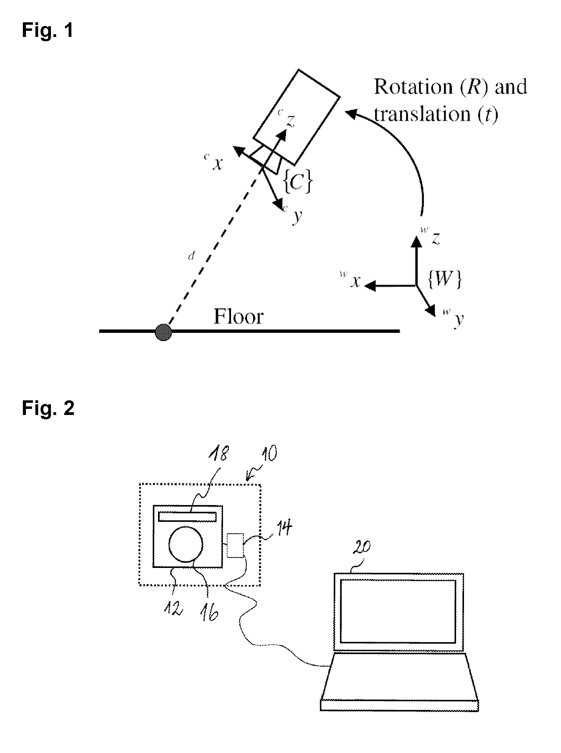
[0027]FIG. 2 shows a schematic illustration of a 3D TOF camera system 10, comprising a 3D TOF camera 12 and an image processor 14 (shown as an element separate from the camera 12, but which may also be incorporated with it in the same housing). The camera comprises an optical imaging system, illustrated by lens 16, and an illumination unit, illustrated by LED array 18, for illuminating the scene to be imaged with modulated or pulsed light. The camera system also comprises a hardware interface, e.g. a USB port, a firewire port, etc. (not shown in the drawing) allowing the connection of a user interface (in this case a laptop computer 20)

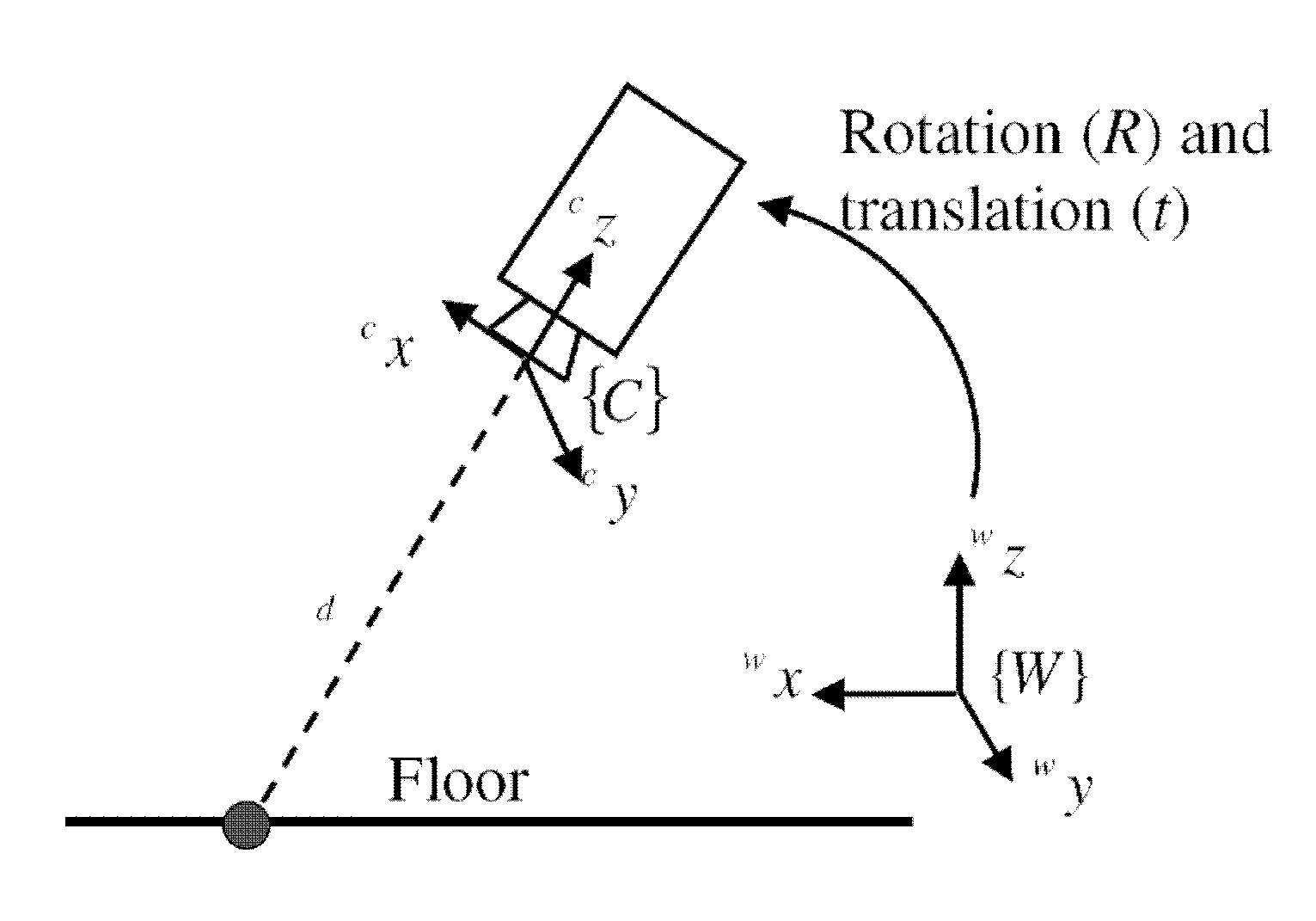
[0028]Range images acquired with a 3D TOF camera correspond to matrices of distance values d, which indicate the distances from the camera to the imaged surface elements. Given the internal camera parameters of the camera (e.g. focal length, principal point of the camera, and distortion parameters), the 3D coordinates c[X,Y,Z]T of the visible surface ...


PUM


Abstract

A camera system comprises a 3D TOF camera for acquiring a camera-perspective range image of a scene and an image processor for processing the range image. The image processor contains a position and orientation calibration routine implemented therein in hardware and / or software, which position and orientation calibration routine, when executed by the image processor, detects one or more planes within a range image acquired by the 3D TOF camera, selects a reference plane among the at least one or more planes detected and computes position and orientation parameters of the 3D TOF camera with respect to the reference plane, such as, e.g., elevation above the reference plane and / or camera roll angle and / or camera pitch angle.

Description

TECHNICAL FIELD[0001]The present invention generally relates to the technical field of 3D computer vision, in particular to a position / orientation calibration method for a 3D time-of-flight camera system.BACKGROUND[0002]As used herein, a 3D time-of-flight camera (hereinafter “3D TOF camera” or simply “camera”) designates a camera that acquires images (herein called “range images”) containing distance information pertaining to a scene by using the time-of-flight measurement principle. Such camera generally comprises a light source emitting modulated or pulsed light into the scene to be imaged in 3D and a pixel array on which the scene is imaged by an optical system. The camera then correlates the light detected in the pixels with the light emitted and determines, for each pixel, the phase difference between emitted and received light, or the difference between emission and reception times. These quantities are proportional to the radial distance between the camera and the part of the...

Claims


Application Information

Patent Timeline
Patent Type & Authority Applications(United States)
IPC IPC(8): H04N13/02
CPCG01S7/4972G01S17/08G06T2207/30196G06T7/0018G06T2207/10028G01S17/89G06T7/80G01S17/894
Inventor GARCIA, FREDERICGRANDIDIER, FREDERICMIRBACH, BRUNOORSELLO, ROBERTOSOLIGNAC, THOMAS
Owner IEE INT ELECTRONICS & ENG SA
Why Eureka
Try Eureka