Gps-based measurement of roll rate and roll angle of spinning platforms

a technology of rolling platform and measurement angle, which is applied in the direction of measurement devices, instruments, satellite radio beaconing, etc., can solve the problems of inability to spin faster than the bandwidth of the actuator, inability to fully control the projectile, and high cost of traditional methods of measuring roll rate and angle, etc., and achieve the effect of low cos

Active Publication Date: 2010-05-13
MAYFLOWER COMM CO INC
View PDF15 Cites 71 Cited by
  • Summary
  • Abstract
  • Description
  • Claims
  • Application Information

AI Technical Summary

Benefits of technology

[0014]The present invention provides a low cost means of measuring the roll angle and roll rate of spinning platforms. Two or more antennas are installed on this platform, and their output signals processed through the usual RF front end of a GPS receiver.

Problems solved by technology

Since the command to lift the spinning projectile in a particular geographic direction is transformed into the projectile's body coordinates for execution by its control actuators, such as aerodynamic fins, this means that a fully controlled projectile—or at least that section of it that houses the control system—cannot be spinning faster than the bandwidth of its actuators.
Traditional methods of measuring roll rate and angle are expensive, and can be justified only for very high value platforms.
Inertial rate indicators, including MEMS (MEMS=Micro Electro Mechanical Systems) gyroscopes, are relatively expensive on this scale of costs.
More importantly, they require calibration prior to use, which adds to the procurement cost.
Magnetometers, likewise, are expensive, besides also being susceptible to interference from local magnetic fields, such as from on-board electromagnetic actuators and other components.

Method used


Image

  • Gps-based measurement of roll rate and roll angle of spinning platforms
  • Gps-based measurement of roll rate and roll angle of spinning platforms
  • Gps-based measurement of roll rate and roll angle of spinning platforms

Examples


Embodiment Construction

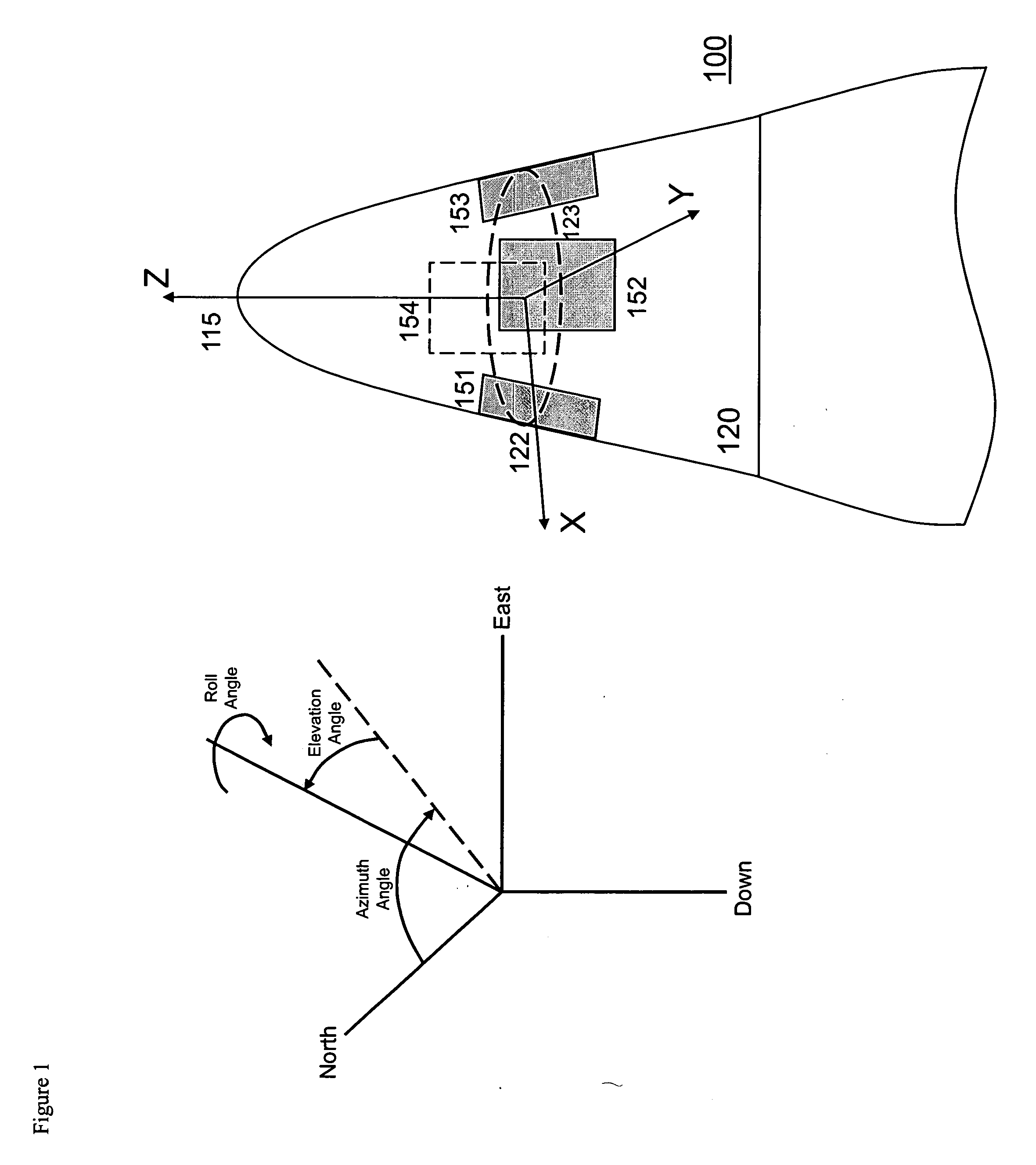
[0042]FIG. 1 shows the front end body 120 of a notional projectile 100, with its four-antenna array comprising the antennas 151, 152, 153, 154 attached to the body 120 of the projectile 100. The antennas 151, 152, 153, 154 in FIG. 1 are pointed in different directions. Although this diagram is based on a four-antenna system, an antenna array comprising any multiplicity of antennas, two or greater, can be used. For a platform in the typical projectile configuration 100 shown in FIG. 1, these antennas are preferably disposed about the circumference 122 of the body 120 at a selected location 123 of its spin axis 115. For small platforms, the spacing between the antennas can be small fractions of the GPS wavelength. The orientation of the projectile 100 may be defined by a set of three Euler angles, Azimuth, Elevation and Roll (FIG. 1).

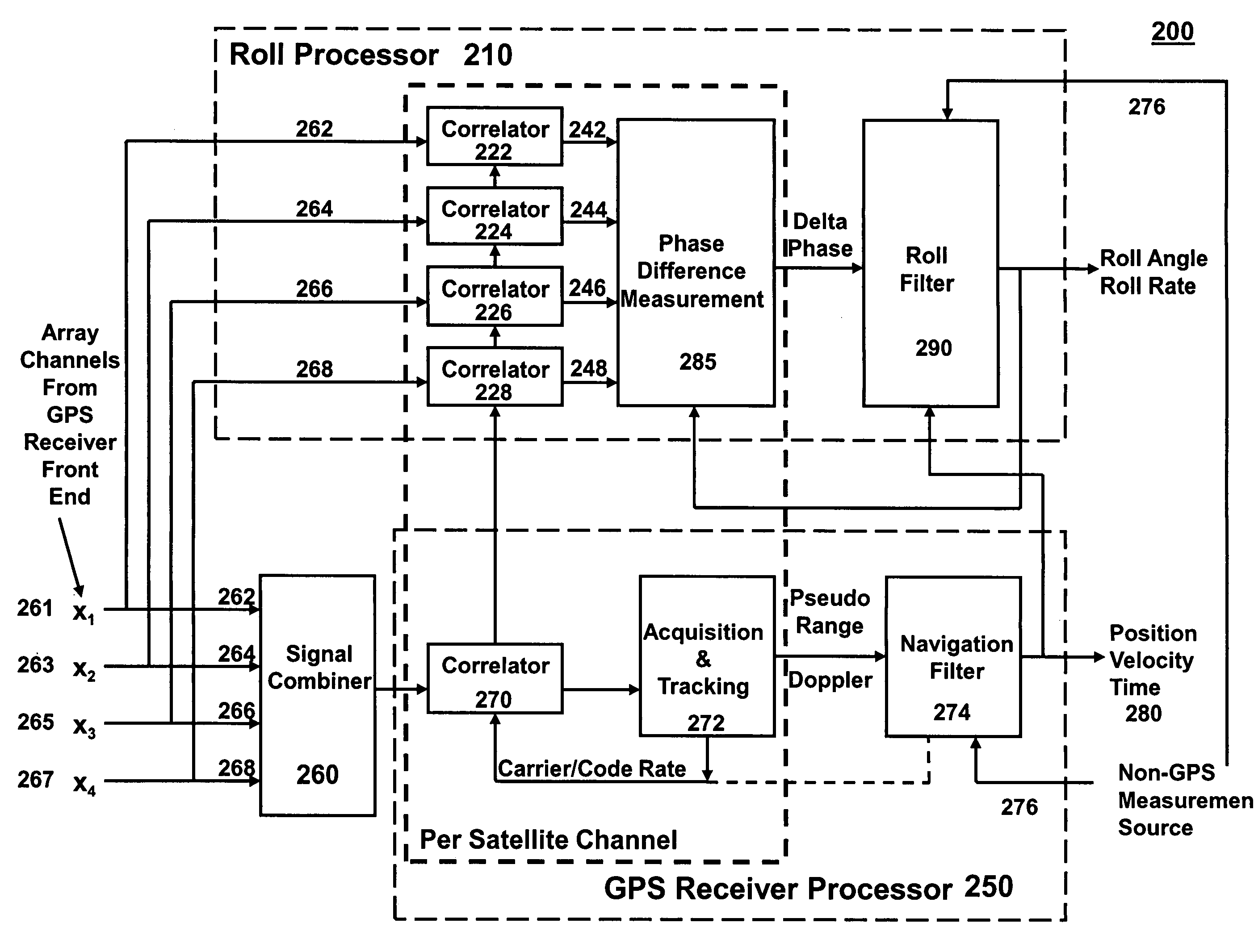
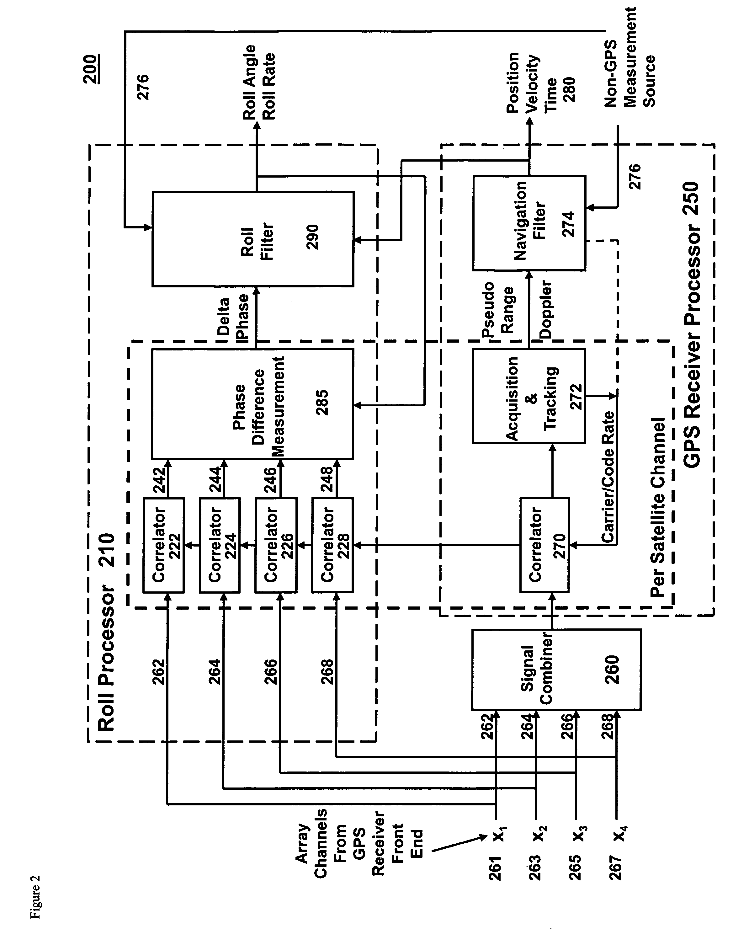
[0043]The preferred GPS receiver architecture 200 for a four-antenna array of the present invention is shown in FIG. 2. The standard GPS navigation funct...


PUM


Abstract

A system and method for determining the roll rate and roll angle of a spinning platform, using the measured phase differences between the GPS satellite signals received on two or more antennas. The measured phase differences and the navigation solution from a GPS receiver are processed in a Kalman filter to obtain the desired information. Data from non-GPS measurement sources is optionally provided to update the navigation solution. Although of wide applicability, the invention is uniquely suited to the measurement of roll rates and roll angles of fast spinning platforms with small baselines, in which the antennas are separated from each other by distances that are a fraction of the GPS signal wavelength.

Description

BACKGROUND OF THE INVENTION[0001]The present invention deals generally with measurements of the roll rate and roll angle of spinning platforms, including spinning projectiles, spin stabilized spacecraft, and other such vehicles, using the signals transmitted by the satellites of the Global Positioning System (GPS).[0002]In the context of this application, the term “roll” is understood to mean the platform's rotation about its spin axis. The words “platform,”“vehicle,” and “projectile” are used interchangeably in this specification and are to be interpreted as inclusive, so that the mention of one also means the mention of the others. The term GPS also is to be construed broadly, and includes not only GPS but all Global Navigation Satellite Systems (GNSS) using CDMA (Code Division Multiple Access) technology.[0003]The focus on roll results from the fact that many projectiles aimed at a distant target do not require a full attitude reference system. If the projectile is stable under a...

Claims


Application Information

Patent Timeline
Patent Type & Authority Applications(United States)
IPC IPC(8): G01S19/14G01S19/25
CPCG01S19/54G01S19/48
Inventor VELDE, WALLACE VANDERCAFARELLA, JOHNTSENG, HUAN-WANDIMOS, GEORGEUPADHYAY, TRIVENI
Owner MAYFLOWER COMM CO INC
Why Eureka
Try Eureka