Multi-antenna GNSS control system and method

a control system and multi-antenna technology, applied in process and machine control, navigation instruments, instruments, etc., can solve the problems of inability to accurately determine poi, less than precise production, and inability to take into account the actual curvature of the terrain, etc., to achieve accurate and economical pre-planned effects

Active Publication Date: 2013-11-12
AGJUNCTION
View PDF429 Cites 73 Cited by
  • Summary
  • Abstract
  • Description
  • Claims
  • Application Information

AI Technical Summary

Benefits of technology

[0008]Disclosed herein in an exemplary embodiment is a sensor system for vehicle steering control comprising: a plurality of global navigation satellite systems (GNSS) including receivers and antennas at a fixed spacing to determine a vehicle position, velocity and at least one of a heading angle, a pitch angle and a roll angle based on carrier phase corrected real time kinematic (RTK) position differences. The roll angle facilitates correction of the lateral motion induced position errors resultant from motion of the antennae as the vehicle moves based on an offset to ground and the roll angle. The system also includes a control system configured to receive the vehicle position, heading, and at least one of roll, pitch and yaw, and configured to generate a steering command to a vehicle steering system.
[0013]An additional exemplary embodiment is a sensor system for vehicle guidance using one or more global navigation satellite systems (GNSSs) according to the above-mentioned embodiments, in combination with a plurality of various sensors located throughout a vehicle and a towed implement. These sensors detect additional parameters from those calculated by the GNSS positioning system, such as vehicle and implement stress levels, fuel levels, power levels, optical guide path observations via an onboard camera, multi-section (articulated) implement position and attitude sensing via multiple antennas and other characteristics of the working vehicle. The combination of the two systems results in a much more accurate and economical preplanned path generated for use in later field work.

Problems solved by technology

However, in existing satellite positioning systems (SATPS) for guided parallel and contour swathing for precision farming, mining, and the like, the actual curvature of terrain may not be taken into account.
This results in a less than precise production because of the less than precise parallel or contour swathing.
However, if the tractor is on an inclined terrain with a variable tilt, which is often the case, the SATPS alone cannot determine the terrain tilt so the POI also cannot be determined.
This results in a guidance error because the POI is approximated by the point of reception (POR), and this approximation worsens as the terrain inclination increases.
This results in cross track position excursions relative to the vehicle ground track which would contaminate any attempt to guide to a defined field line or swath.
Systems using Doppler radar will encounter errors with the radar and latency.
Similarly, gyroscopes, which may provide heading, roll, or pitch measurements, may be deployed as part of an inertial navigation package, but tend to encounter drift errors and biases and still require some external attitude measurements for gyroscope initialization and drift compensation.
Gyroscopes have good short-term characteristics but undesirable long-term characteristics, especially those gyroscopes of lower cost such as those based on a vibrating resonator.
Similarly, inertial systems employing gyroscopes and accelerometers have good short-term characteristics but also suffer from drift.
Various systems include navigating utilizing GNSS; however, these systems also exhibit disadvantages.
Existing GNSS position computations may include lag times, which may be especially troublesome when, for example, GNSS velocity is used to derive vehicle heading.
Existing GNSS systems do not provide high quality heading information at slower vehicle speeds.
However, accuracy and precision can only improve the efficiency of working vehicles, such as those in the agricultural field, to a limited extent.
Although such systems are able to track and guide vehicles in three dimensions, including along ridges and sloped-regions, errors may appear in other aspects of a working vehicle.

Method used


Image

  • Multi-antenna GNSS control system and method
  • Multi-antenna GNSS control system and method
  • Multi-antenna GNSS control system and method

Examples


Embodiment Construction

I. GNSS Introduction

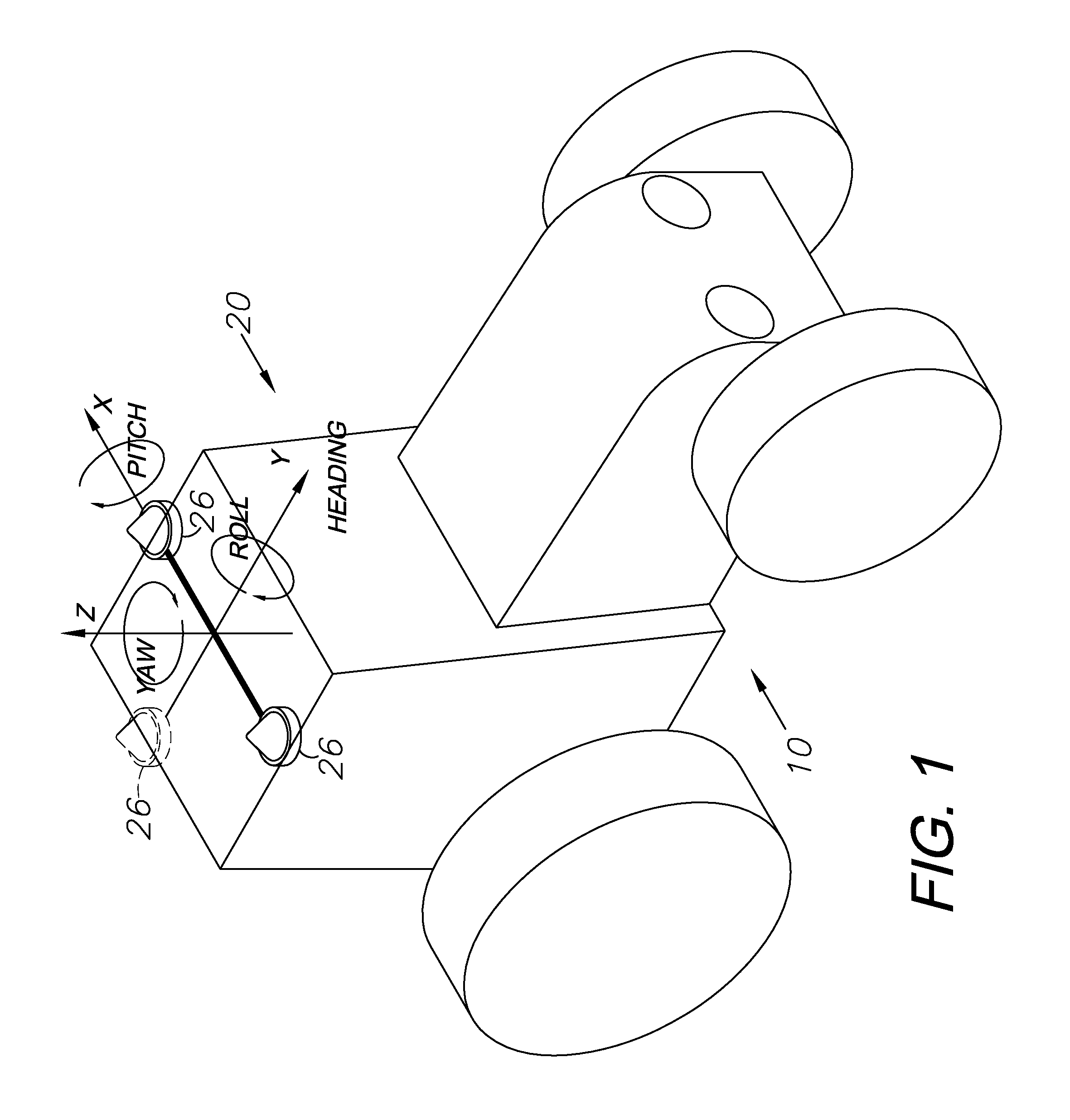
[0046]Global navigation satellite systems (GNSS) are broadly defined to include GPS (U.S.), Galileo (proposed), GLONASS (Russia), Beidou / Compass (China, proposed), IRNSS (India, proposed), QZSS (Japan, proposed) and other current and future positioning technology using signals from satellites, with or without augmentation from terrestrial sources. Inertial navigation systems (INS) include gyroscopic (gyro) sensors, accelerometers and similar technologies for providing output corresponding to the inertia of moving components in all axes, i.e. through six degrees of freedom (positive and negative directions along transverse X, longitudinal Y and vertical Z axes). Yaw, pitch and roll refer to moving component rotation about the Z, X and Y axes respectively. Said terminology will include the words specifically mentioned, derivatives thereof and words of similar meaning.

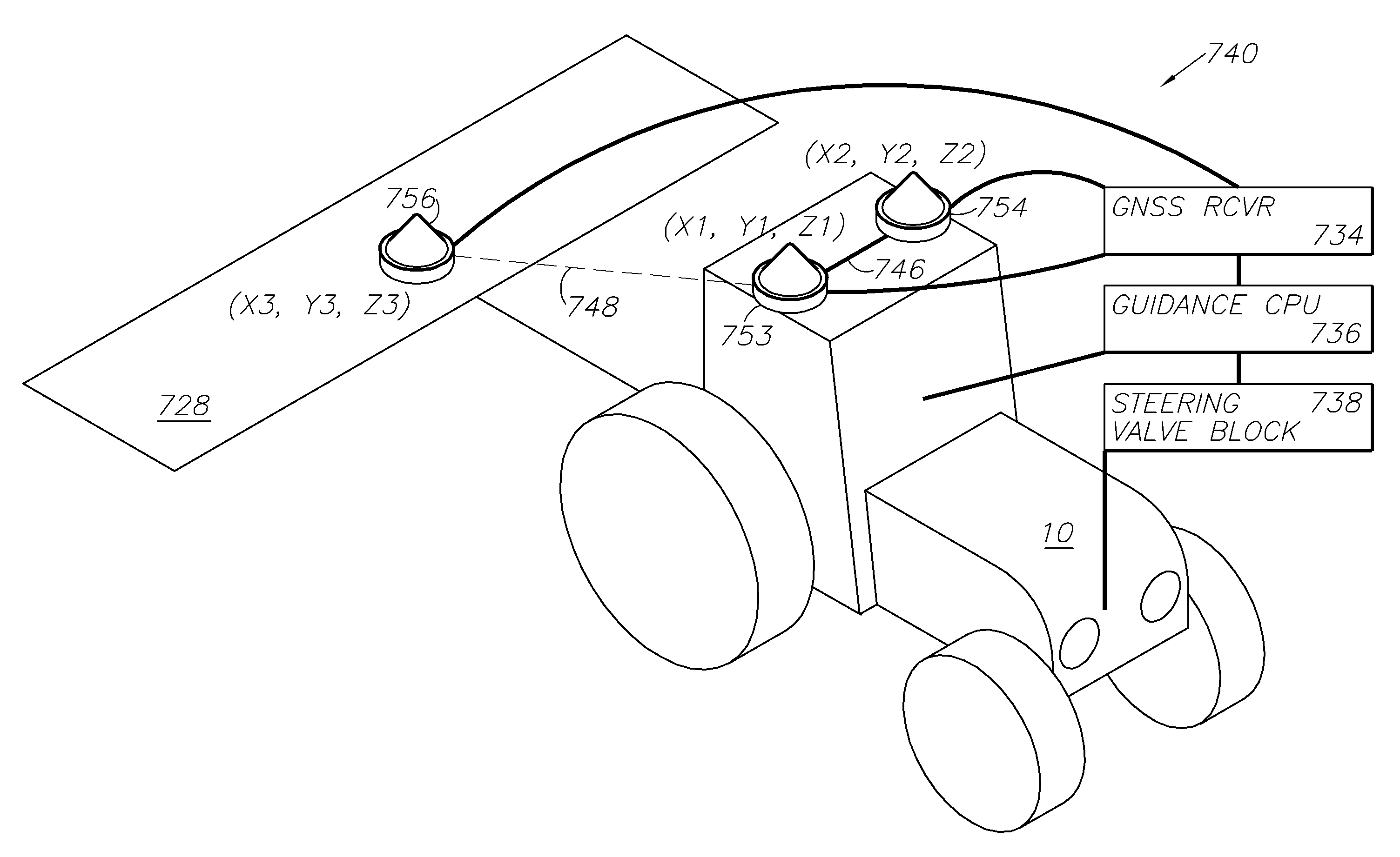
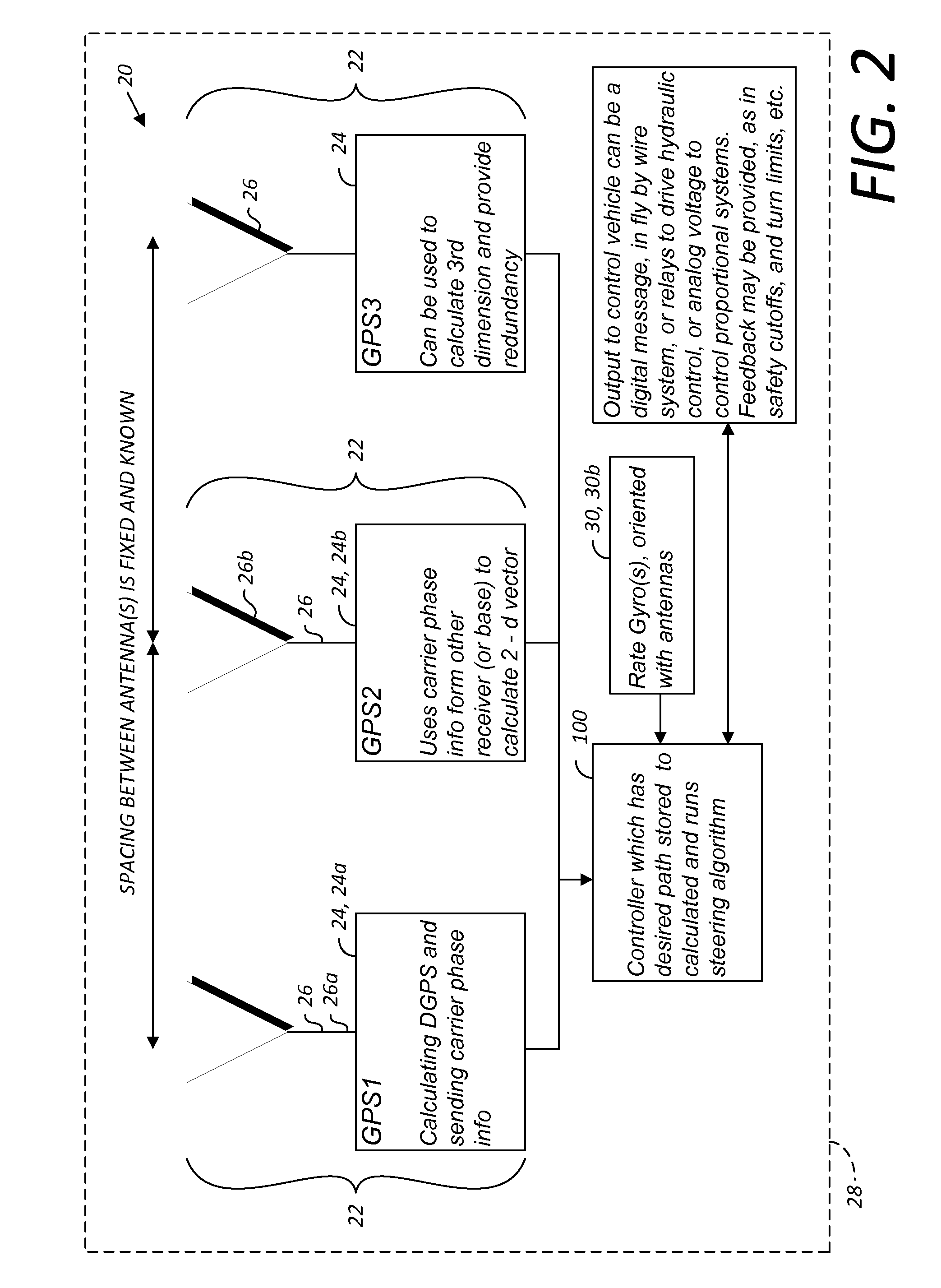
[0047]Disclosed herein in an exemplary embodiment is a sensor system for vehicle guidance. The sens...


PUM


Abstract

A global navigation satellite sensor system (GNSS) and gyroscope control system for vehicle steering control comprising a GNSS receiver and antennas at a fixed spacing to determine a vehicle position, velocity and at least one of a heading angle, a pitch angle and a roll angle based on carrier phase position differences. A vehicle control method includes the steps of computing a position and a heading for the vehicle using GNSS positioning and a rate gyro for determining vehicle attitude, which is used for generating a steering command.

Description

CROSS-REFERENCE TO RELATED APPLICATIONS[0001]This application is a continuation-in-part of and claims the benefit of: U.S. patent application Ser. No. 12 / 355,776, filed Jan. 17, 2009 now U.S. Pat. No. 8,140,223, which is a continuation-in-part of Ser. No. 12 / 171,399, filed Jul. 11, 2008 now U.S. Pat. No. 8,265,826, which is a continuation-in-part of No. 10 / 804,758, filed Mar. 19, 2004, now U.S. Pat. No. 7,400,956; Ser. No. 10 / 828,745, filed Apr. 21, 2004; and U.S. Provisional Patent Applications No. 60 / 456,146, filed Mar. 20, 2003 and No. 60 / 464,756, filed Apr. 23, 2003. The contents of all of the aforementioned applications are incorporated by reference herein in their entireties.BACKGROUND OF THE INVENTION[0002]Movable machinery, such as agricultural equipment, open-pit mining machines, airplane crop dusters and the like all benefit from accurate global navigation satellite system (GNSS) high precision survey products, and others. However, in existing satellite positioning systems...

Claims


Application Information

Patent Timeline
Patent Type & Authority Patents(United States)
IPC IPC(8): G01C21/00
CPCA01B69/007A01B79/005G01S5/0063G01S5/0247G01S19/14G01S19/35G01S19/43G01S19/53G05D1/027G05D1/0278G05D1/0259G05D2201/0201
Inventor WHITEHEAD, MICHAEL L.MILLER, STEVEN R.MCCLURE, JOHN A.FELLER, WALTER J.
Owner AGJUNCTION
Why Eureka
Try Eureka