
Comparing patterns

a pattern and pattern technology, applied in the field of comparing patterns, can solve the problems of reducing performance, reducing computational complexity, and reducing the number of features

Active Publication Date: 2009-08-04
BRITISH TELECOMM PLC
View PDF56 Cites 8 Cited by
  • Summary
  • Abstract
  • Description
  • Claims
  • Application Information

AI Technical Summary

Benefits of technology

[0105]This method also has the advantage of being able to detect multiple disparities in which image A is compared with images B1,B2,B3 etc. This would be useful in the case of CCTV intruder detection in which image frames B1,B2,B3 etc would be typical examples of different atmospheric conditions and other normal background states, and an alarm would be raised only if disparities were detected in all the normal image frames.

Problems solved by technology

In many cases, the number of features leads to a computationally unmanageable process and Principal Components Analysis and other techniques are used to scale down the problem without significantly reducing performance (e.g., see partek.com website / index.html).
These approaches achieve great success in non-noisy environments, but fail when the pattern variability and number of pattern classes increase.

Method used


Image

  • Comparing patterns
  • Comparing patterns
  • Comparing patterns

Examples


example 1

Optical Character Recognition (FIG. 4)

[0084]An image A of the letter B is compared with images B1-B5, of the letters A, B, C, D and E. The rank ordered average scores Va correspond to B, D, E, C, A. The results were generated with t=50, s=3 and ε=2.

example 2

Embedded Recognition (FIG. 5)

[0085]An image A of an ‘X’ shape is compared with another image B1 containing 9 smaller shapes including an ‘X’. The ‘X’ shape is again compared with image B2 with the same 9 shapes except for the small ‘X’ which is altered. The average scores Va are 27.5 and 11.9 respectively, indicating the presence of ‘X’ features in the first and less in the second. The individual scores V for the respective comparisons are shown in the charts. The results were generated with t=50, s=7 and ε=2. A more complicated example of embedded recognition is the identification of known faces in a crowd of people.

example 3

Trade Mark Retrieval (FIG. 6)

[0086]An image A of a special cross shape is first compared with 4 basic shapes B1-B4 including a large cross, each basic pattern representing clusters of similar shapes with high scores between each other. The large cross generates the largest average score Va (43.6). The same special cross in then compared with 4 varieties of cross B5-B8 including a small version of itself (B5) which obtains a maximum score of 50. The chart provides the values of (50−V) for each picture element in the comparison with the large cross—the tall columns indicate the disparity with the ends of the lower legs of the cross. The results were generated with t=50, s=7 and ε=2.


PUM


Abstract

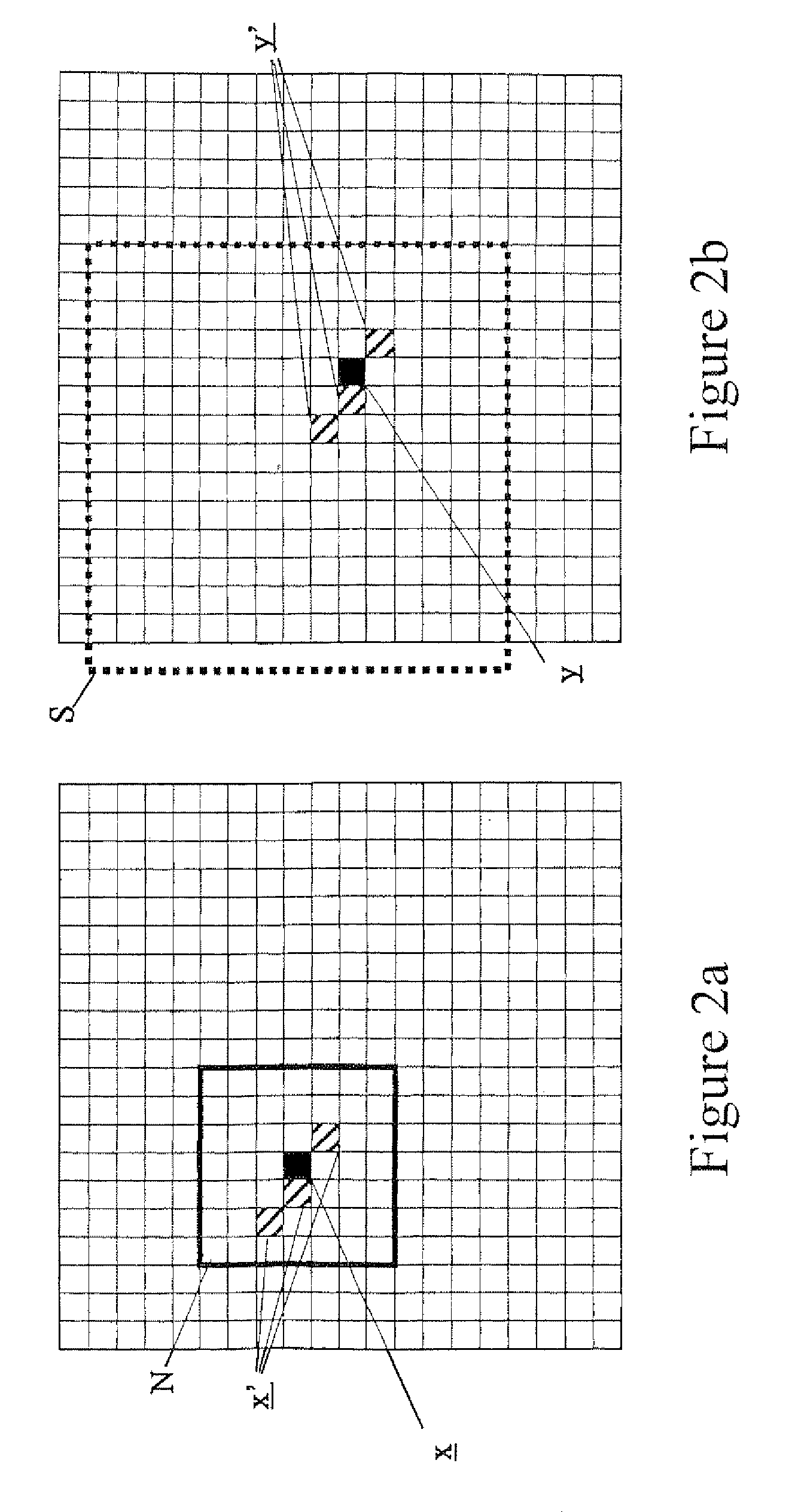
A first image (or other pattern) is represented by a first ordered set of elements A each having a value and a second pattern is represented by a second such set. A comparison of the two involves performing, for each of a plurality of elements x of the first ordered set the steps of selecting from the first ordered set a plurality of elements x′ in the vicinity of the element x under consideration, selecting an element y of the second ordered set and comparing the elements x′ of the first ordered set with elements y′ of the second ordered set (each of which has the same position relative to the selected element y′ of the second ordered set as a respective one x′ of the selected plurality of elements of the first ordered set has relative to the element x under consideration). The comparison itself comprises comparing the value of each of the selected plurality of elements x′ of the first set with the value of the correspondingly positioned element y′ of the like plurality of elements of the second set in accordance with a predetermined match criterion to produce a decision that the plurality of elements of the first ordered set matches the plurality of elements of the second ordered set. The comparison is them repeated with a fresh selection of the plurality of elements x′ of the first set and / or a fresh selection of an element y of the second ordered set generating a similarity measure V as a function of the number of matches. Preferably, following a comparison resulting in a match decision, the next comparison is performed with a fresh selection of the plurality of elements x′ of the first set and the same selection of an element y of the second set.

Description

[0001]This application is the U.S. national phase of international application PCT / GB03 / 01209 filed 21 Mar. 2003 which designated the U.S. and claims benefit of EP 02252097.7, dated 22 Mar. 2002, the entire content of which is hereby incorporated by reference.BACKGROUND[0002]1. Technical Field[0003]The present invention is concerned with comparing one pattern with another, and is of particular interest in the comparison of two-dimensional patterns such as visual images, although applicable also to one-dimensional patterns and patterns having three or more dimensions.[0004]2. Related Art[0005]Standard approaches to pattern recognition use templates to recognize and categorize patterns [1]. Such templates take many forms, but they are normally produced by a statistical analysis of training data and matched with unseen data using a similarity measure [2]. The statistical analysis is normally carried out over a number of intuitively selected features that appear to satisfy the needs of ...

Claims


Application Information

Patent Timeline
IPC IPC(8): G06K9/68G06K9/62G06K9/00G06K9/64G06T7/00
CPCG06K9/6211G06V10/757G06T7/00G06F18/00
Inventor STENTIFORD, FREDERICK W M
Owner BRITISH TELECOMM PLC
Learn More