Generator control arrangement

a technology of generators and control arrangements, applied in the direction of electric generator control, dynamo-electric converter control, instruments, etc., can solve the problem of temporarily abandoning the parallel operation of electrical generators

Active Publication Date: 2009-08-11
ROLLS ROYCE PLC
View PDF13 Cites 8 Cited by
  • Summary
  • Abstract
  • Description
  • Claims
  • Application Information

AI Technical Summary

Benefits of technology

[0018]Typically, a switch is provided to alternate between the specific processor gain value at zero and a specific processo

Problems solved by technology

However, parallel operation of the electrical generators may be temporarily abandoned, either specifically to meet electrical demands or under fault conditions when one or more of the electrical generators may malfunction.
In suc

Method used


Image

  • Generator control arrangement
  • Generator control arrangement
  • Generator control arrangement

Examples


Embodiment Construction

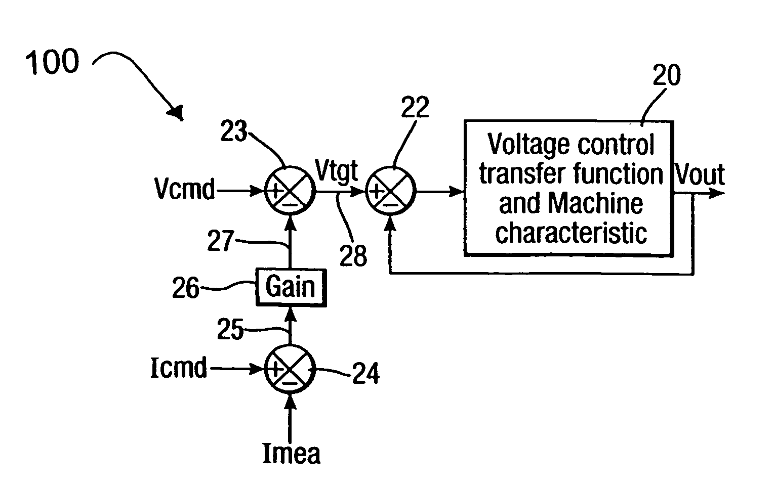
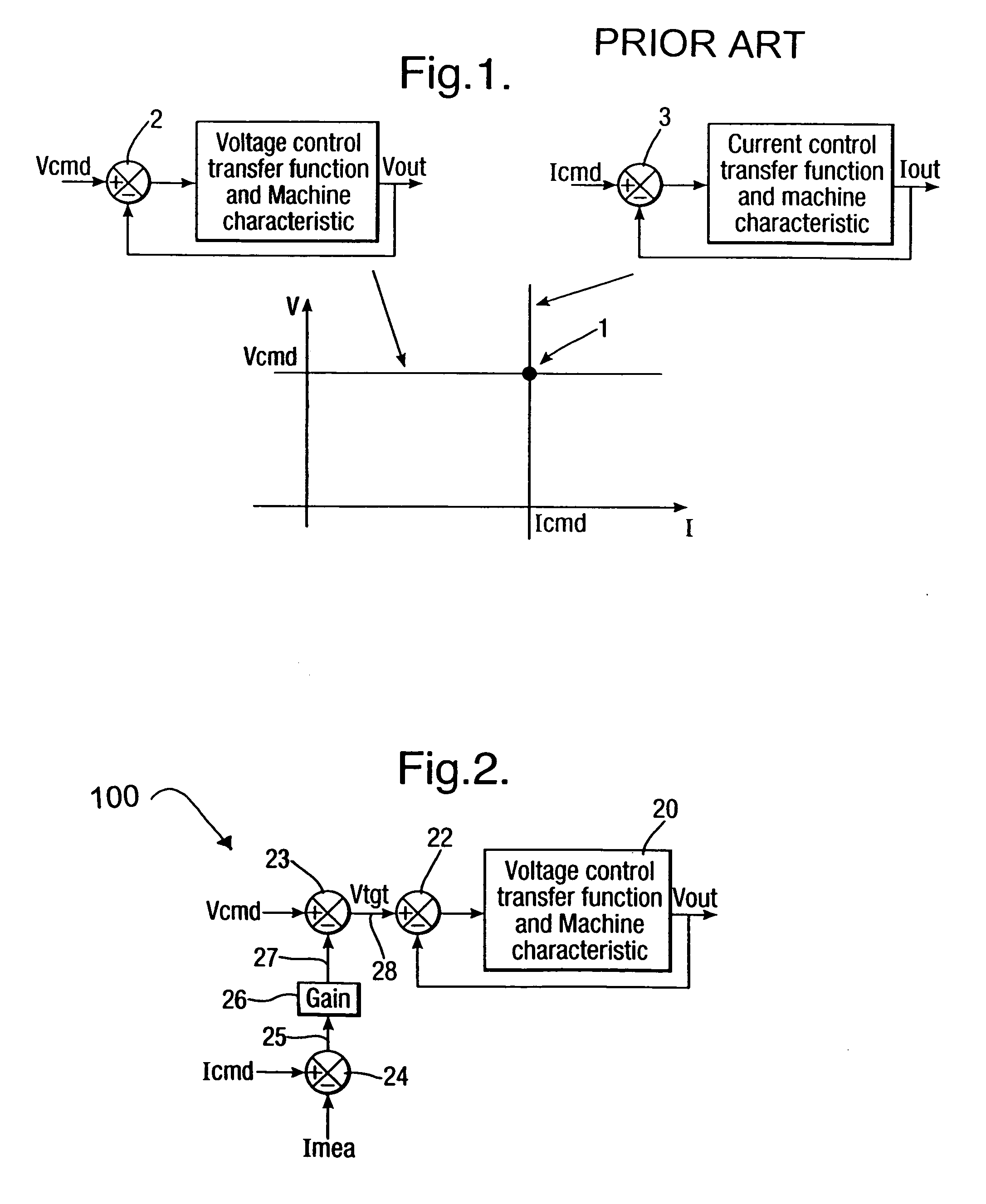
[0024]As indicated above, generator control arrangements which operate upon voltage control regulation are known. These voltage control arrangements effectively compare the output voltage Vout with the target voltage Vtgt in order that any divergence can be identified by a controller device and adjustments made to the generator in order to achieve the desired voltage output, that is to say Vtgt=Vout. In such circumstances these voltage control arrangements incorporate feed-back to a comparator where the comparison between Vtgt and Vout is made.

[0025]In accordance with aspects of the present invention, the Vtgt value is provided through a transfer comparator. This transfer comparator will receive a reference voltage value consistent with the target voltage value Vtgt along with a product of an error factor between a reference electrical current and an actual measured electrical current subject to a specific processor gain.

[0026]FIG. 2 illustrates a generator control arrangement, or c...


PUM


Abstract

A generator control arrangement for an electrical power generator, the arrangement comprising a controller arranged to regulate output voltage from a generator to a target value, the controller including a voltage comparator for comparing a presented voltage with a desired output voltage, the presented voltage derived in a transfer comparator by combination of a reference voltage value and an error value between a reference electrical current value and a measured electrical current value subject to a processor gain whereby the processor gain can be specifically set at zero to enable control by voltage or the processor gain can be specifically set at greater than zero to enable control by electrical current.

Description

FIELD OF THE INVENTION[0001]The present invention relates to a generator control arrangement and more particularly to a control arrangement for electrical power generators utilised in gas turbine engines.BACKGROUND OF THE INVENTION[0002]Use of electrical power generators is quite extensive with a wide range of applications. It will be understood that these electrical power generators typically take drive from a primary mover in the form of an engine and therefore create electrical power for control and actuation of that engine as well as for other functions ancillary to the engine or vehicle or structure in which the engine is located. With regard to gas turbine engines it will be appreciated that a significant number of such engines are utilised in aerospace applications. In such circumstances a gas turbine engine is utilised in order to drive the electrical power generator to provide electrical power to both the engine for control and actuator functions as well as with respect to ...

Claims


Application Information

Patent Timeline
IPC IPC(8): H02P9/48H02P9/46
CPCH02P5/74H02P9/305H02P2101/30G05F1/10H02P9/00
Inventor TRAINER, DAVID RHU, LIHUAHIRST, MICHAEL P
Owner ROLLS ROYCE PLC
Why Eureka
Try Eureka