Apparatus equipped with an optical keyboard and optical input device

a technology of optical input device and keyboard, which is applied in the direction of electronic switching, pulse technique, instruments, etc., can solve the problems of radiation source relative cost components, radiation interference, and space occupied by the housing and the detector, so as to increase the distance between the diode laser and the device window, increase the reliability of the output signal of the input device, and increase the distance

Inactive Publication Date: 2009-08-11
KONINKLIJKE PHILIPS ELECTRONICS NV
View PDF8 Cites 21 Cited by
  • Summary
  • Abstract
  • Description
  • Claims
  • Application Information

AI Technical Summary

Benefits of technology

[0009]The apparatus is based on the insight that measuring beam of the input device can be used also for detecting whether a key of the optical keyboard is a pushed condition and on the insight that the reliability of the output signal of the input device can be considerably increased by increasing the distance between the diode laser and the device window. The diode laser of the input is arranged such that the measuring beam passes all key positions before it reaches the window of the input device.
[0015]This input device uses the recently obtained insight that hitherto unused information present in a sensor unit, which is used for measuring a scroll movement, can be used to determine the presence of a finger on the input window. If such a presence is established, it can be concluded that a click movement, which includes a short rest of the finger on the window, takes place. By using a same sensor unit for measuring both scroll and click movement, a sensor unit can be saved, which means costs and space reduction for the input device, and thus for the apparatus.

Problems solved by technology

Because some of the scattered radiation enters into the laser cavity through the laser mirror, in the laser cavity interference of radiation takes place.
Each of the radiation sources is accommodated in an own housing and the space occupied by these housings and by the detectors may become a problem, especially in hand-held apparatus.
Moreover the radiation sources are relative expensive components and consume much electrical energy.
As in hand-held apparatus the energy is supplied by batteries, such batteries should be recharged rather frequently, which is annoying for the user.

Method used


Image

  • Apparatus equipped with an optical keyboard and optical input device
  • Apparatus equipped with an optical keyboard and optical input device
  • Apparatus equipped with an optical keyboard and optical input device

Examples


embodiment 200

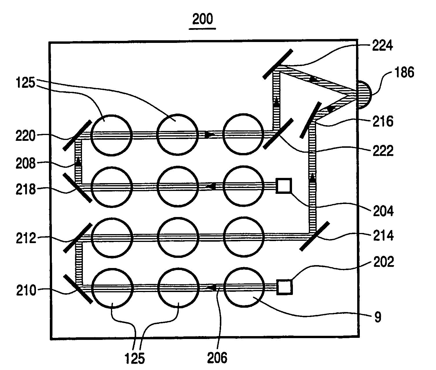
[0111]FIG. 18 shows an embodiment 200 of the optical keyboard with integrated input device, which comprises two diode lasers 202, 204 and associated photo diodes (not shown) . The input device can be used for measuring a click movement and scroll movement either along one axis or along two axes. The keys 125 are now distributed over two groups. The condition of the keys of the first group, the lower group in FIG. 18, is now measured by means of diode laser 202 and the associated detector. The measuring beam 206 from this diode laser is guided along the positions of the keys of the first group by means of mirrors 210 and 212 and is then directed to the device window 186 by means of the mirrors 214 and 216. Diode laser 204 and the associated detector are used to measure the condition of the keys of the second group of keys, the upper group in FIG. 18. The measuring beam 208 is guided along the positions of these keys by means of the mirrors 218 and 220 and is then directed to the devi...

embodiment 230

[0112]FIG. 19 shows an embodiment 230 of the optical keyboard with an integrated optical input device, which comprises three diode lasers 232, 234, 236 and associated photo detectors (not shown) The keys 125 are now distributed over three parallel groups. The diode lasers are arranged relative to the groups such that the measuring beams 238, 239 and 240 pass the positions of the keys of the first (left hand) group, the second (central) group and the third (right hand) group, respectively. Measuring beam 239 is directly incident on device window 186 and measuring beam 238 and measuring beam 240 is directed to this window by means of mirror 244 and mirror 246, respectively. As in the embodiment of FIG. 18, the position of a pressed key is obtained by determining for which one of the measuring beams the radiation path is interrupted and measuring the number of zero-order undulations in the detector signal associated with this measuring beam. The measuring beams 238, 239 and 240 can be ...

embodiment 270

[0114]The invention may also be used in a portable computer, known as notebook or laptop, an embodiment 270 of which is shown in FIG. 21. The notebook comprises a base portion 272 and a cover portion 274 with a LCD display 276. The base portion accommodates the different computer modules and an optical keyboard 278. In this keyboard, an optical input device 280 is arranged which replaces the conventional mouse pad. The input device may be arranged at the position of the conventional mouse pad or at any other easily accessible position. The optical keyboard and the optical input device are integrated as described herein before for a mobile phone apparatus.

[0115]A hand-held computer, for example the type known as personal digital assistant (DPA) is a smaller version of the notebook. Such a handheld computer may also be provided with an optical input device and other optical devices mentioned with respect to the notebook computer. As, moreover a hand-held computer should have smaller w...


PUM


Abstract

An apparatus includes an optical keyboard and an optical input device controlled by a moving object. The input device has at least one diode laser and photo diode for supplying at least one measuring beam to a device window and for receiving radiation reflected by the object placed on the window. The input device may be integrated in the keyboard such that the measuring beam is guided via the positions of the keys to the window.

Description

[0001]This application is a 371 PCT / IB03 / 003571BACKGROUND INVENTION[0002]The invention relates to an apparatus comprising an optical input device controlled by a moving object and an optical keyboard, which input device comprises at least one optical sensor unit comprising a diode laser for supplying a measuring beam and converting means for converting measuring beam radiation reflected by the object into an electric signal, which converting means are constituted by the combination of a laser cavity and measuring means for measuring changes in operation of the laser cavity, which are due to interference of reflected measuring beam radiation re-entering the laser cavity and the optical wave in this cavity and which are representative of the movement of the object.DESCRIPTION OF PRIOR ART[0003]An optical keyboard is understood to mean a keyboard having movable keys (buttons) and a flat light guide arranged under the keyboard surface and provided with means to guide radiation along the...

Claims


Application Information

Patent Timeline
Patent Type & Authority Patents(United States)
IPC IPC(8): G06F3/02G06F1/16G06F3/00G06F3/033G06F3/0354H03K17/969
CPCG06F1/1616G06F1/1626G06F1/1662H03K17/969G06F3/0202G06F3/0213G06F1/169
Inventor LIESS, MARTIN DIETER
Owner KONINKLIJKE PHILIPS ELECTRONICS NV
Why Eureka
Try Eureka