Particulate matter detection system and method

a technology of particle matter and detection system, which is applied in the direction of exhaust treatment, instruments, material resistance, etc., can solve the problems of inability to accurately detect the particle size of the PM sensor, the mechanics of the accumulation of soot particles on the pm sensor may be much more complicated, and the emission of mainly limited particles, so as to maintain the service life and reduce thermal stress. , the effect of increasing the reliability of the outpu

Active Publication Date: 2019-02-21
DELPHI TECH IP LTD
View PDF2 Cites 0 Cited by
  • Summary
  • Abstract
  • Description
  • Claims
  • Application Information

AI Technical Summary

Benefits of technology

[0007]Briefly described, a method of operating a particulate matter sensor having a pair of spaced apart electrodes and a heater is provided. The method includes accumulating particulate matter on the particulate matter sensor, thereby changing resistance between the pair of spaced apart electrodes, wherein the particulate matter sensor provides a signal that varies based upon an amount of the particulate matter on the particulate matter sensor. The particulate matter sensor includes a sensing cycle that includes a deadband zone in which the resistance is greater than a first predetermined value, followed by an active zone in which the resistance is less than or equal to the first predetermined value, which is followed by a regeneration zone in which the heater is operated to elevate the temperature of the particulate matter sensor to a first predetermined temperature for a first predetermined time in order to oxidize the particulate matter accumulated on the particulate matter sensor, thereby returning the sensing cycle to the deadband zone. The method also includes interrupting the sensing cycle with a modified regeneration zone in which the heater is operated to elevate the temperature of the particulate matter sensor in order to oxidize the particulate matter accumulated on the particulate matter sensor, thereby returning the sensing cycle to the deadband zone, wherein the modified regeneration zone includes at least one of 1) elevating the temperature of the particulate matter sensor to a second predetermined temperature which is greater than the first predetermined temperature and 2) elevating the temperature of the particulate matter sensor for a second predetermined time which is longer than the first predetermined time. The method increases the reliability of the output of the PM sensor while maintaining the service live longevity that is desired of the PM sensor by minimizing thermal stress to which the PM sensor is subjected.

Problems solved by technology

Particulate matter emissions are typically limited by emissions regulations and it is common for modern diesel engines to be equipped with a particulate filter.
However, the assumption that the step-like changes of the PM sensor signal represents large particle strikes or blow-offs is not quite correct since detailed analysis of the disturbance indicates that the mechanics of accumulation of soot particles on the PM sensor may be much more complicated and include, for example, partial separation followed by secondary re-settling at the surface of the PM sensor in the form of conglomerates of the soot particles originally representing a dimension within the size of the normal spectrum.
This phenomenon is generally associated with the ineffective oxidation, i.e. cleaning, of the PM sensor during the sensor regeneration period.
Consequently, such a scenario makes the conversion of the measured soot deposit rate into soot concentration very difficult, since the parasitic effect of partial deposit separation is purely random and results from corrupted adhesion to the PM sensor with byproducts of an incomplete cleaning process.
While increasing the temperature and exposure time during regeneration may increase the effectiveness of regeneration, thereby increasing the reliability of the detection capability of the PM sensor, the increased temperature and exposure time may have undesirable consequences on the service life of the PM sensor.

Method used


Image

  • Particulate matter detection system and method
  • Particulate matter detection system and method
  • Particulate matter detection system and method

Examples


Embodiment Construction

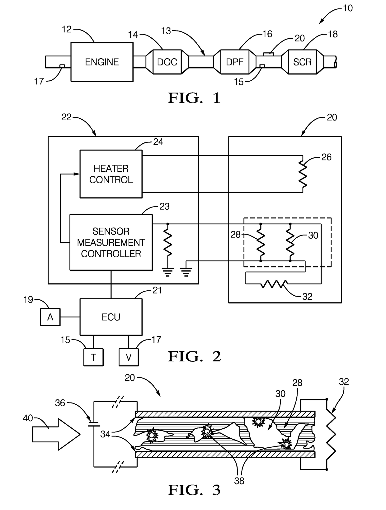
[0034]An example vehicle powertrain system 10 is shown in FIG. 1. The system 10 includes an engine 12, which in this non-limiting exemplary embodiment is a diesel engine, fluidly connected to an exhaust system 13 that includes a diesel oxidation catalyst (DOC) 14 and a diesel particulate filter (DPF) 16. A selective catalyst reduction (SCR) catalyst, such as those used in conjunction with a urea injection system, is arranged downstream from the DPF 16.

[0035]A particulate matter (PM, also referred to as “soot”) sensor 20 is arranged in the exhaust system 13, typically in proximity to the DPF 16, although it should be understood that the PM sensor 20 may be located elsewhere. The PM sensor 20 is configured to be exposed to the exhaust stream and accumulate PM on its internal sensing element. The PM sensor 20 provides a resistance signal that varies based upon an amount of the PM on the sensor.

[0036]An exhaust gas temperature sensor 15 is arranged in the exhaust stream in proximity to ...


PUM

PropertyMeasurementUnit
temperatureaaaaaaaaaa
bias voltage Vb1aaaaaaaaaa
sensor resistanceaaaaaaaaaa

Abstract

A method of operating a particulate matter sensor having a pair of spaced apart electrodes and a heater includes accumulating particulate matter on the sensor, thereby changing resistance between the pair of spaced apart electrodes. The particulate matter sensor includes a sensing cycle that includes a deadband zone, followed by an active zone, which is followed by a regeneration zone in which the heater is operated to elevate the temperature of the particulate matter sensor to a first predetermined temperature for a first predetermined time in order to oxidize the particulate matter accumulated on the particulate matter sensor. The method also includes interrupting the sensing cycle with a modified regeneration zone which is either higher in temperature or length than the regeneration zone.

Description

TECHNICAL FIELD OF INVENTION[0001]This disclosure relates to a system and method of detecting particulate matter using a particulate matter sensor throughout a particulate matter sensor measurement cycle; and more particularly to system and method which utilizes a modified regeneration when conditions are met.BACKGROUND OF INVENTION[0002]Rich combustion conditions, such as those which occur in diffusion flame processes that are present in diesel engines and other internal combustion engines, produce particulate matter, which is carried in its exhaust stream. Particulate matter emissions are typically limited by emissions regulations and it is common for modern diesel engines to be equipped with a particulate filter. As part of the emissions regulations, diagnosis of the particulate filter is mandated and the use of a particulate matter sensor is one such diagnostic system. Thus, it is desirable to accurately measure particulate matter real-time in vehicles to ensure that the engine ...

Claims


Application Information

Patent Timeline
Patent Type & Authority Applications(United States)
IPC IPC(8): G01N27/16
CPCG01N27/16F01N11/00G01N15/0656F01N2560/05F01N2560/20
Inventor MALACZYNSKI, GERARD WLADYSLAWROTH, GREGORY THOMAS
Owner DELPHI TECH IP LTD
Why Eureka
Try Eureka