Vibrating wire viscosity sensor

a technology of viscosity sensor and vibrating wire, which is applied in the field of fluid property measurement, can solve the problems of reducing the accuracy of viscosity measurement, affecting the accuracy of the viscosity measurement,

Active Publication Date: 2009-08-18
SCHLUMBERGER TECH CORP
View PDF5 Cites 34 Cited by
  • Summary
  • Abstract
  • Description
  • Claims
  • Application Information

AI Technical Summary

Problems solved by technology

For a well producing ten barrels of water for one barrel of oil, it is therefore a challenge to obtain the true viscosity of the hydrocarbon produced, as such measurements are typically dominated by the properties of the majority phase, namely that of water.
Several measurement principles have been attempted in the past to measure the viscosity of flowing fluids encountered in the hydrocarbon industry and other industries, but each technique has associated weaknesses.
One such technique uses NMR measurements wherein the viscosity of reservoir fluids can be deduced, but the accuracy is usually considered to be no better than an order of magnitude without additional modification of the interpretation based on information concerning the local oilfield environment.
For incompressible fluids the viscosity can be accurately measured granted a known flown rate and the pressure drop along a flow line, but flow rate measurements are notorious for being inaccurate, decreasing the accuracy of the viscosity measurement.

Method used


Image

  • Vibrating wire viscosity sensor
  • Vibrating wire viscosity sensor
  • Vibrating wire viscosity sensor

Examples


Embodiment Construction

[0022]Various embodiments and aspects of the invention will now be described in detail with reference to the accompanying Figures. This invention is not limited in its application to the details of construction and the arrangement of components set forth in the following description or illustrated in the drawings. The invention is capable of various alternative embodiments and may be practiced using a variety of other ways. Furthermore, the terminology and phraseology used herein is solely used for descriptive purposes and should not be construed as limiting in scope. Language such as “including,”“comprising,”“having,”“containing,” or “involving,” and variations herein, are intended to encompass the items listed thereafter, equivalents, and additional items not recited. As used herein the term “fluid channel” shall include any element capable of containing a fluid regardless of cross sectional shape.

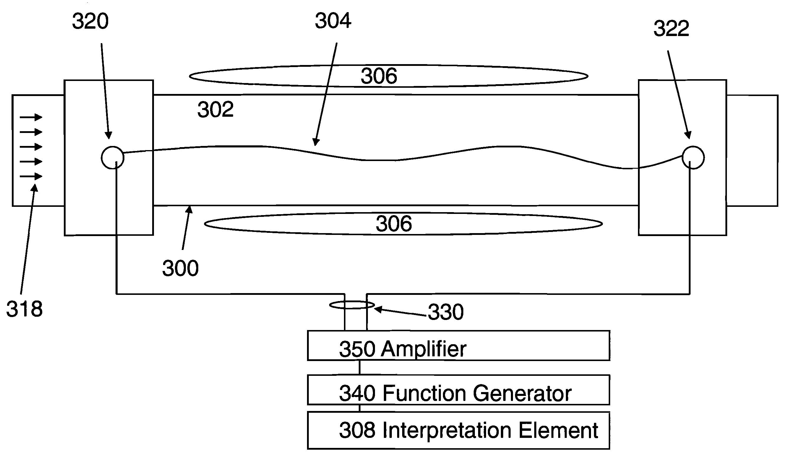
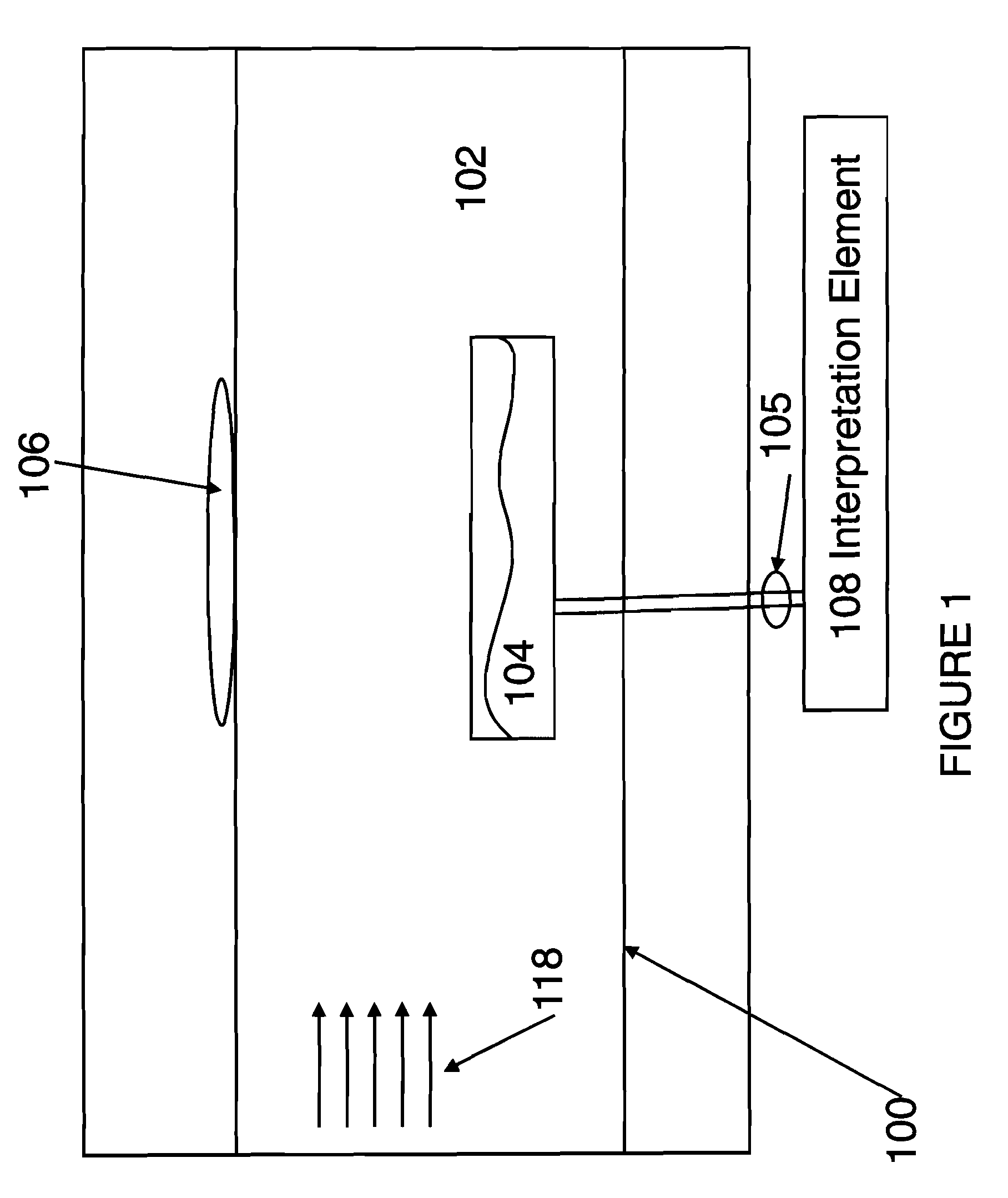
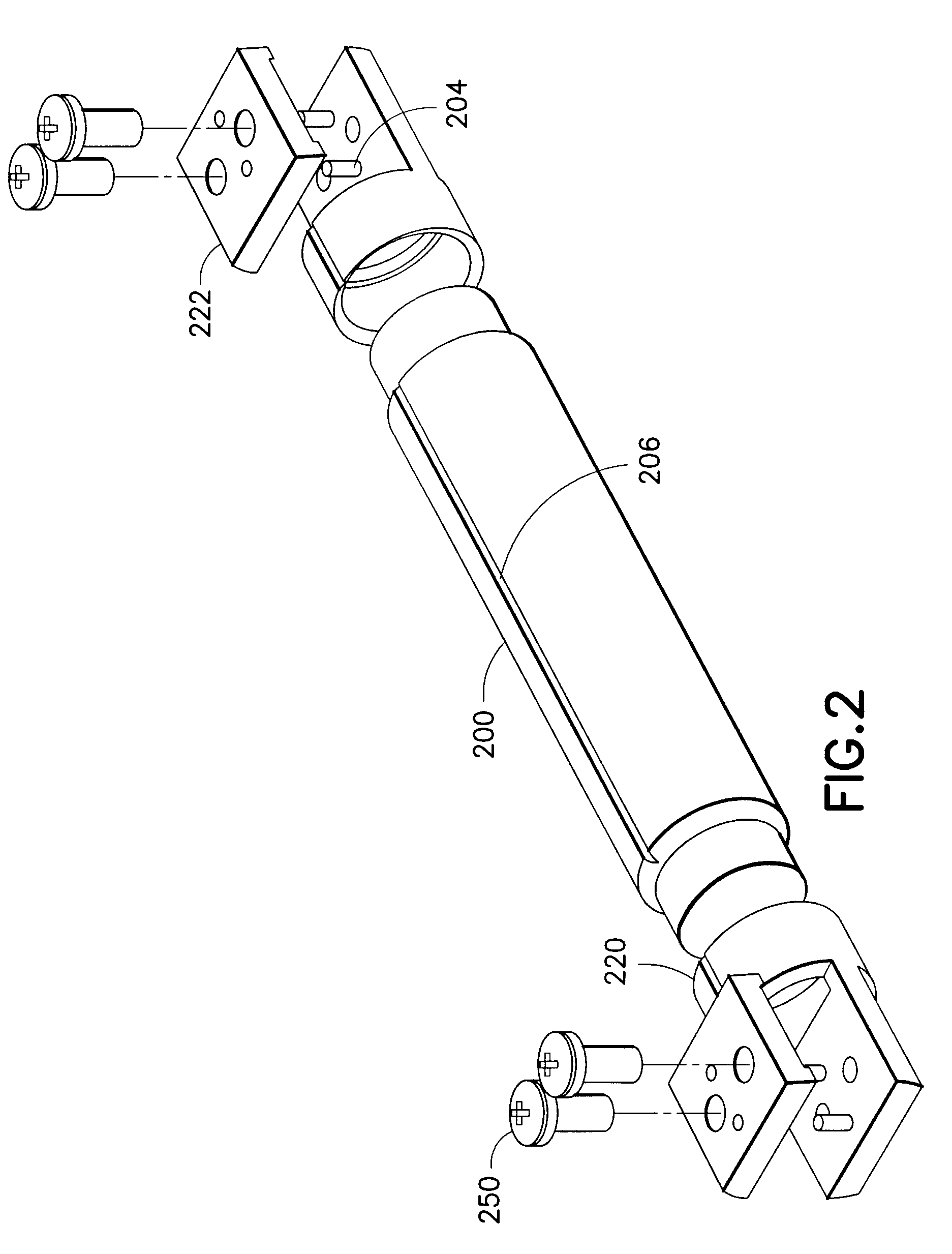
[0023]The present invention recites a vibrating wire based method, system and appara...


PUM

PropertyMeasurementUnit
radiusaaaaaaaaaa
viscosityaaaaaaaaaa
viscositiesaaaaaaaaaa

Abstract

A method and apparatus for providing, e.g., identifying or determining, at least one parameter of a fluid moving through a fluid channel using a vibrating wire in contact with the fluid moving through the fluid channel that is clamped under tension. The vibrating wire is actuated by an actuating device capable of displacing the vibrating wire from an initial position. An interpretation element further is utilized to provide a parameter of the fluid moving through the fluid channel based upon data from the vibrating wire following actuation by the actuation element.

Description

BACKGROUND OF THE INVENTION[0001]1. Field of the Invention[0002]The present invention relates generally to the measurement of a property of a fluid, and more particularly the measurement of a property such as but not limited to viscosity of a fluid in a reservoir. For the purpose of clarity the present invention addresses hydrocarbon reservoirs and production setting, but is applicable to a variety of reservoir applications.[0003]2. Background of the Invention[0004]Measurement of a physical property of a gas, or liquid or fluid has numerous applications in residential and commercial settings. One such physical property of interest may be the viscosity of the fluid, which is central to a variety of industries and applications, including hydrocarbon production and exploration. Measurement of the physical properties of a fluid may be beneficial in gas flows, liquid flows or some combination of both gas and liquid flow. Furthermore, the flow may be a single phase or multi-phase flow. Wh...

Claims


Application Information

Patent Timeline
Patent Type & Authority Patents(United States)
IPC IPC(8): G01N11/00
CPCG01N11/16G01N29/036G01N29/222G01N29/4418G01N2291/02818G01N33/28G01N2291/015
Inventor HARRISON, CHRISTOPHERETCHART, ISABELLEHSU, KAIJUNDT, JACQUESGOODWIN, ANTHONY ROBERT HOLMESGODEFROY, SOPHIESULLIVAN, MATTHEWFORNARI, ANTOINE
Owner SCHLUMBERGER TECH CORP
Why Eureka
Try Eureka