System for measuring the frequency of a vibrating wire sensor using a digital counter system

Inactive Publication Date: 2012-05-17
DS TECH CO LTD
View PDF1 Cites 8 Cited by
  • Summary
  • Abstract
  • Description
  • Claims
  • Application Information

AI Technical Summary

Benefits of technology

[0027]The system according to the present invention enables a substantial reduction in calculations performed by a processor, as compared with a conventional system which employs an analog-to-digital converter.
[0028]Further, the system according to the present invention reduces processor power consumption and may eliminate a circuit of the analog-to-digital converter, thereby simplifying a circuit configuration and reducing power consumption.
[0029]Further, in installation of a wireless system for remote monitoring which has been re

Problems solved by technology

With development of technology, building and civil engineering structures are becoming increasingly complex and large in scale.
However, a monitoring system based on an optical cable has a complex structure, suffers from installation difficulty, and requires expensive equipment.
Thus, systems based on an optical cable are not generally adopted in the art.
Since this manner requires continuous sampling of analog outputs corresponding to the intrinsic vibration signals output from the vibrating wire, the processor inevitably

Method used


Image

  • System for measuring the frequency of a vibrating wire sensor using a digital counter system
  • System for measuring the frequency of a vibrating wire sensor using a digital counter system
  • System for measuring the frequency of a vibrating wire sensor using a digital counter system

Examples


example 2

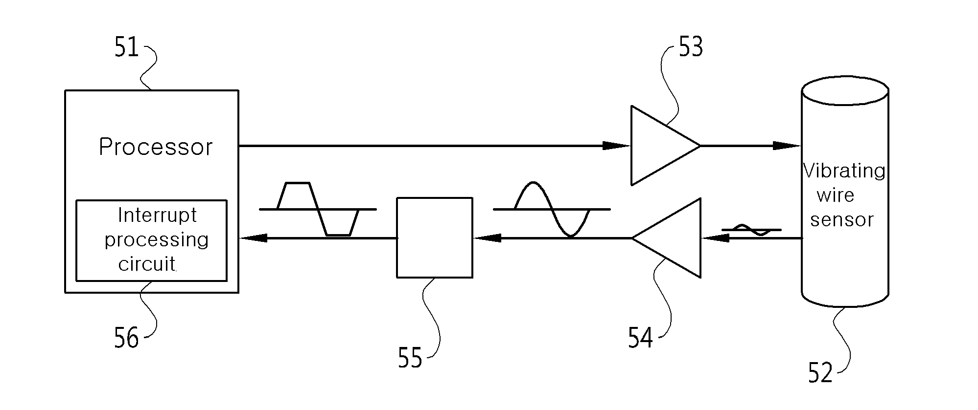
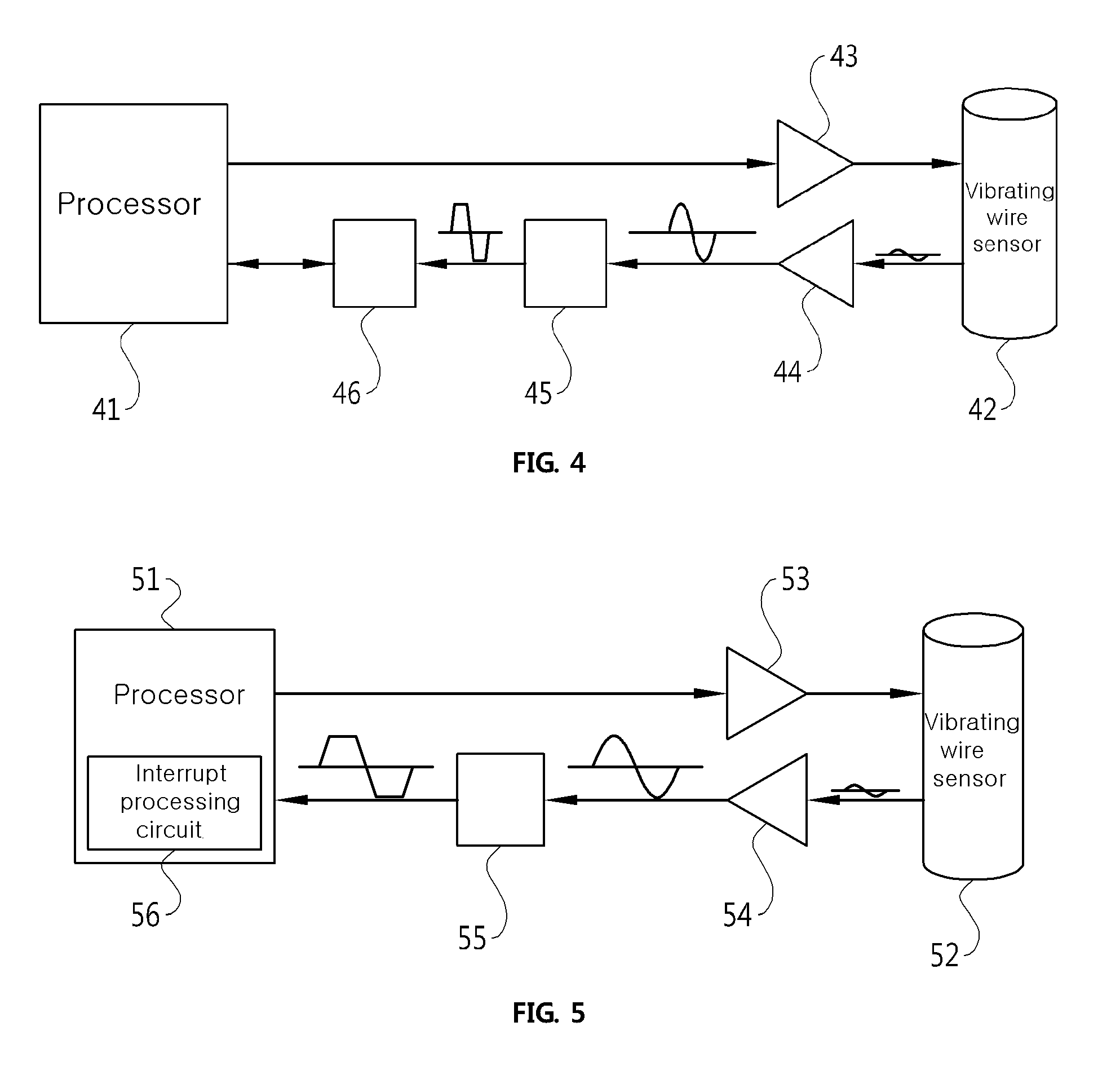
[0068]FIG. 5 is a diagram of a system for measuring a frequency of a vibrating wire sensor according to another embodiment of the present invention.

[0069]Referring to FIG. 5, the system for measuring a frequency of a vibrating wire sensor according to this embodiment includes a processor 51 which outputs an excitation signal to the excitation signal interface unit 53 for the vibrating wire sensor, counts the number of digital inherent vibration signals input from the signal converting unit 55 described below in an interrupt manner, and compares a counted value with consumed time to calculate a resonant frequency; an excitation signal interface unit 53 for the vibrating wire sensor, which receives the excitation signal from the processor 51, converts the received signal into a signal capable of exciting the vibrating wire sensor, and outputs the converted signal; a vibrating wire sensor 52 which outputs an intrinsic vibration signal in response to the excitation signal; a received si...


PUM


Abstract

The present invention relates to a system for measuring the frequency of a vibrating wire sensor using a digital counter system, which measures changes in the length of a structure to monitor changes in the structure, comprising: a processor which outputs an excitation signal to an excitation signal interface unit for a vibrating wire sensor, and compares the counted value input from an external source with a consumed time to calculate a resonant frequency; said excitation signal interface unit for a vibrating wire sensor, which receives the excitation signal from the processor, converts the received signal into a form capable of generating an excitation, and outputs the converted signal; said vibrating wire sensor, which outputs an intrinsic vibration signal in response to the excitation signal; a received signal interface unit for the vibrating wire sensor, which receives an intrinsic vibration signal output by the vibrating wire sensor, converts the received signal into a signal recognizable by the processor, and outputs the converted signal to the processor; a signal-converting unit which converts the amplified intrinsic vibration signal into a digital signal; and a counter which counts the digital intrinsic vibration signal output from the signal converting unit and outputs the counted value to the processor.

Description

TECHNICAL FIELD[0001]The present invention relates to a system for measuring a frequency of a vibrating wire sensor using a digital counter. More specifically, the present invention relates to a system for measuring a frequency of a vibrating wire sensor using a digital counter for monitoring variation of a structure through measurement of changes in the length of the structure.BACKGROUND ART[0002]With development of technology, building and civil engineering structures are becoming increasingly complex and large in scale. Thus, it is becomingly important to monitor security of such structures.[0003]A variety of sensors are used to monitor security of buildings and civil engineering structures. A vibrating wire sensor is one example of such sensors.[0004]A vibrating wire sensor is used in various fields to measure changes in the length of a structure. In addition to the vibrating wire sensor, an optical cable is used to measure changes in the length of a structure. However, a monito...

Claims


Application Information

Patent Timeline
IPC IPC(8): G01H13/00
CPCG01H13/00G01H17/00G01R23/02
Inventor KIM, JONGMOON
Owner DS TECH CO LTD
Why Eureka
Try Eureka