Method and apparatus to create a sound field

a technology of sound field and acoustic antenna, which is applied in the direction of sound producing devices, color television, television systems, etc., can solve the problem of not being able to reproduce the whole signal to be outpu

Inactive Publication Date: 2009-06-25
CAMBRIDGE MECHATRONICS
View PDF62 Cites 79 Cited by
  • Summary
  • Abstract
  • Description
  • Claims
  • Application Information

AI Technical Summary

Benefits of technology

[0016]Thus, there is provided a method and apparatus for applying two types of delay to each sound channel to alleviate the effect of different travelling distances for each channel.
[0096]Another way of modifying the signal uses digital filters (ADF) whose group delay and magnitude response vary in a specified way as a function of frequency (rather than just a simple time delay or level change)—simple delay elements may be used in implementing these filters to reduce the necessary computation. This approach allows control of the DPAA radiation pattern as a function of frequency which allows control of the radiation pattern of the DPAA to be adjusted separately in different frequency bands (which is useful because the size in wavelengths of the DPAA radiating area, and thus its directionality, is otherwise a strong function of frequency). For example, for a DPAA of say 2 m extent its low frequency cut-off (for directionality) is around the 150 Hz region, and as the human ear has difficulty in determining directionality of sounds at such a low frequency it may be more useful not to apply “beam-steering” delays and amplitude weighting at such low frequencies but instead to go for an optimized output level. Additionally, the use of filters may also allow some compensation for unevenness in the radiation pattern of each SET.

Problems solved by technology

Each transducer is capable of creating a sound pressure pulse and is not able to reproduce the whole of the signal to be output.

Method used


Image

  • Method and apparatus to create a sound field
  • Method and apparatus to create a sound field
  • Method and apparatus to create a sound field

Examples


Embodiment Construction

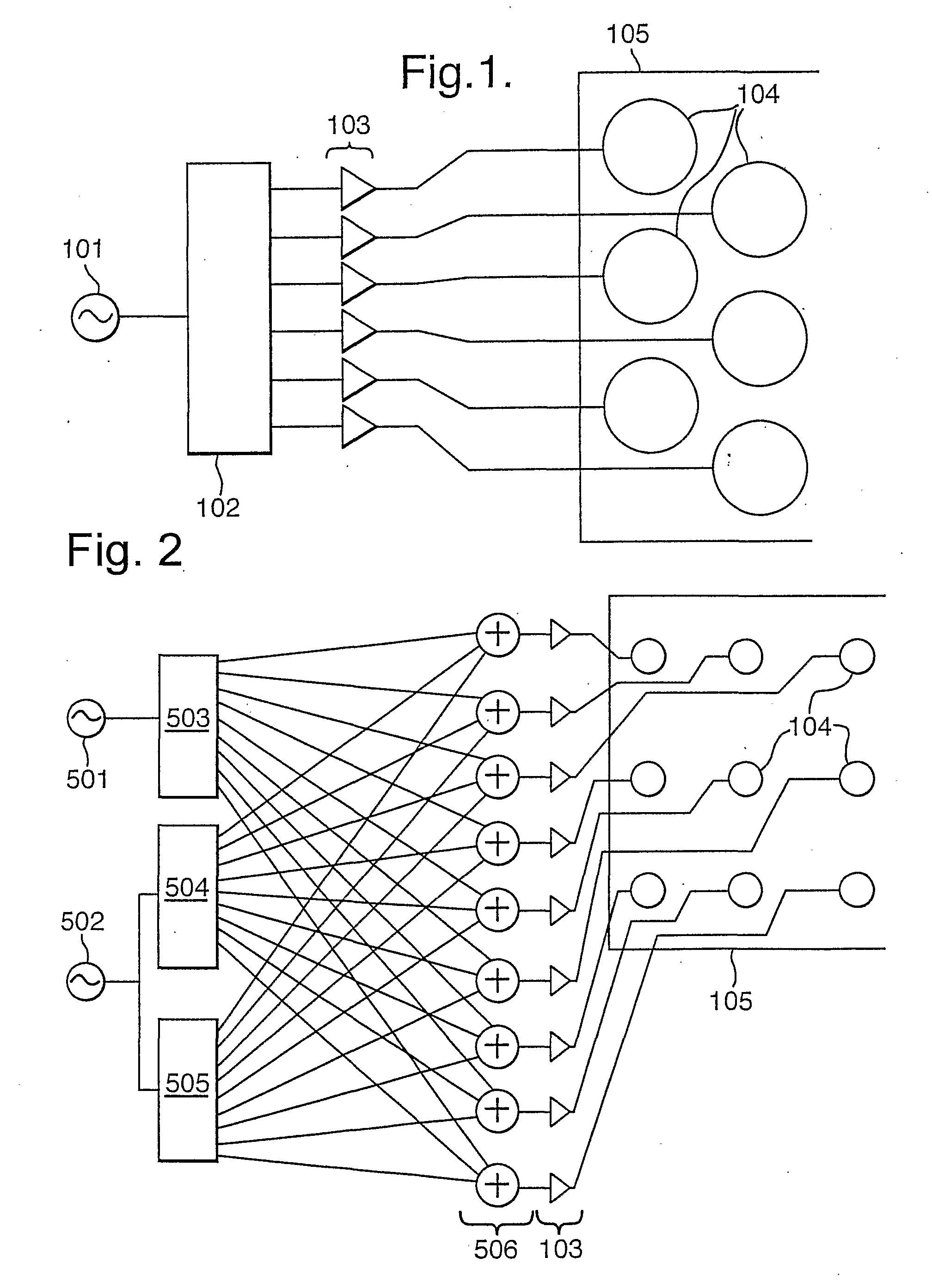
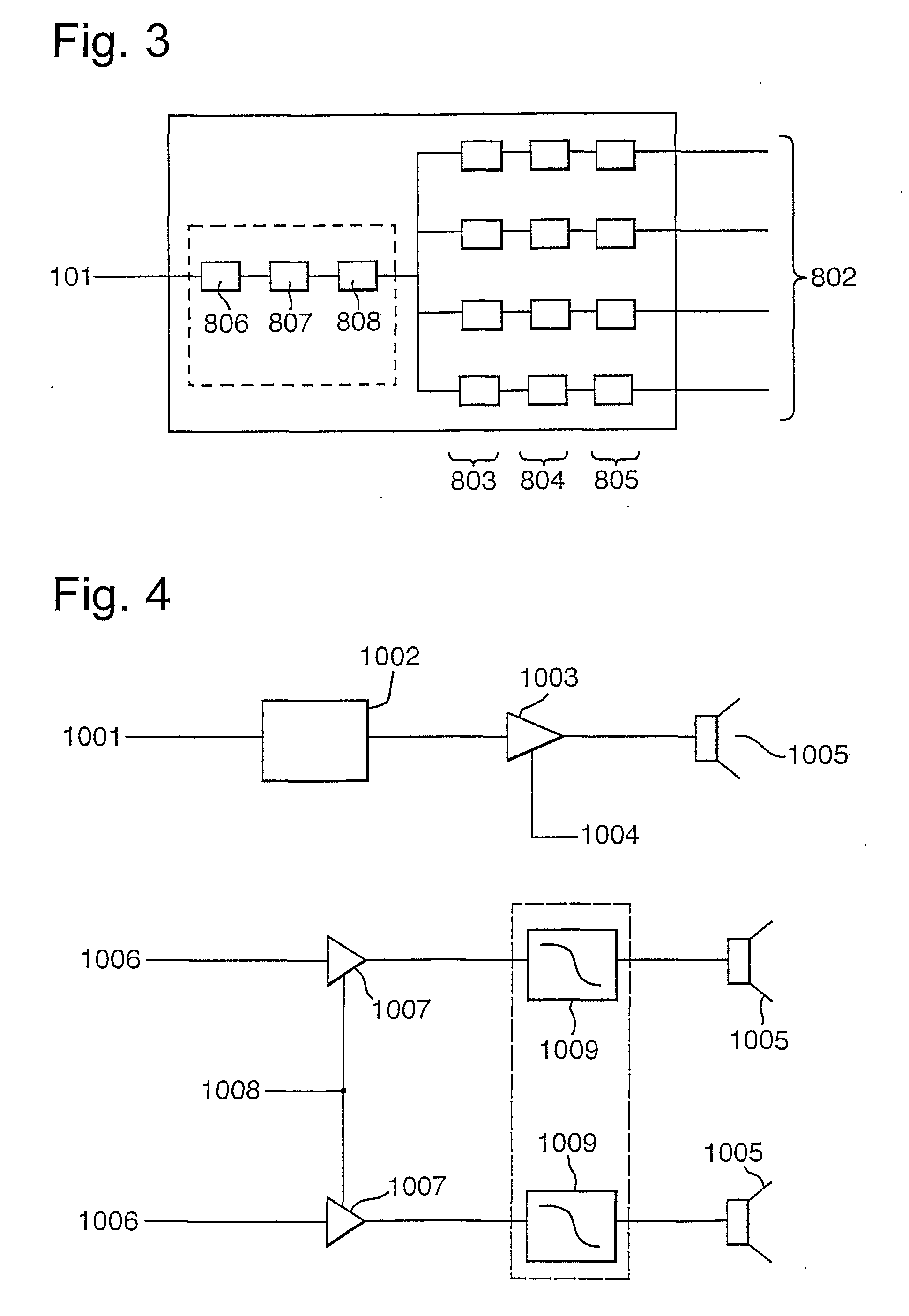
[0266]The description and Figures provided hereinafter necessarily describe the invention using block diagrams, with each block representing a hardware component or a signal processing step. The invention could, in principle, be realised by building separate physical components to perform each step, and interconnecting them as shown. Several of the steps could be implemented using dedicated or programmable integrated circuits, possibly combining several steps in one circuit. It will be understood that in practice it is likely to be most convenient to perform several of the signal processing steps in software, using Digital Signal Processors (DSPs) or general purpose microprocessors. Sequences of steps could then be performed by separate processors or by separate software routines sharing a microprocessor, or be combined into a single routine to improve efficiency.

[0267]The Figures generally only show audio signal paths; clock and control connections are omitted for clarity unless ne...


PUM


Abstract

The invention generally relates to a method and apparatus for taking an input signal, replicating it a number of times and modifying each of the replicas before routing them to respective output transducers such that a desired sound field is created. This sound field may comprise a directed beam, focused beam or a simulated origin. In a first aspect, delays are added to sound channels to remove the effects of different travelling distances. In a second aspect, a delay is added to a video signal to account for the delays added to the sound channels. In a third aspect, different window functions are applied to each channel to give improved flexibility of use. In a fourth aspect, a smaller extent of transducers is used top output high frequencies than are used to output low frequencies. An array having a larger density of transducers near the center is also provided. In a fifth aspect, a line of elongate transducers is provided to give good directivity in a plane. In a sixth aspect, sound beams are focused in front or behind surfaces to give different beam widths and simulated origins. In a seventh aspect, a camera is used to indicate where sound is directed.

Description

CROSS-REFERENCE TO RELATED APPLICATIONS[0001]This application is a continuation of U.S. patent application Ser. No. 10 / 471,451, now U.S. Pat. No. ______, which is a national stage filing under 35 U.S.C. 371 of International Patent Application PCT / GB02 / 01472, which claims the benefit of United Kingdom patent applications GB0108699.1, filed Mar. 27, 2001, and GB 0200291.3, filed Jan. 8, 2002. The entire contents of each of the aforementioned disclosures are hereby incorporated by reference.FIELD OF THE INVENTION[0002]This invention relates to steerable acoustic antennae, and concerns in particular digital electronically-steerable acoustic antennae.BACKGROUND TO THE INVENTION[0003]Phased array antennae are well known in the art in both the electromagnetic and the ultrasonic acoustic fields. They are less well known, but exist in simple forms, in the sonic (audible) acoustic area. These latter are relatively crude, and the invention seeks to provide improvements related to a superior au...

Claims


Application Information

Patent Timeline
Patent Type & Authority Applications(United States)
IPC IPC(8): H04R5/00G10K15/04H04N5/232H04R1/26H04R1/40H04R3/12H04S1/00H04S3/00H04S7/00
CPCF41H13/0081G10K15/04H04R1/26H04R1/403H04R3/12H04S3/002H04R2203/12H04R2205/022H04S1/002H04S3/00H04R2201/401
Inventor HOOLEY, ANTHONYTROUGHTON, PAUL THOMASGOUDIE, ANGUS GAVINEASTON, MARK GEORGEBIENEK, IRVING ALEXANDERDAVIES, JAMESRYAN, DAMON THOMASWINDLE, PAUL RAYMOND
Owner CAMBRIDGE MECHATRONICS
Why Eureka
Try Eureka