Method for Determining the Horizontal Profile of a Flight Plan Complying with a Prescribed Vertical Flight Profile

a flight plan and vertical flight profile technology, applied in the direction of aircraft traffic control, navigation instruments, instruments, etc., can solve the problems of increasing exponentially, requiring very significant computation power, and requiring a minimum cost path

Active Publication Date: 2008-12-11
THALES SA
View PDF12 Cites 83 Cited by
  • Summary
  • Abstract
  • Description
  • Claims
  • Application Information

AI Technical Summary

Benefits of technology

[0008]It is an objective of the present invention to determine, by searching for a lower computation cost, a sequence of check- and/or turn points “D-Fix” defining, with their associated constraints, a flight plan ai

Problems solved by technology

All these methods come up against the difficulty of finding a sequence of individual cells resulting in a minimum cost path, caused by the large number of possible sequences, a number that increases exponentially when the pitch of the geographic location grid is tightened.
Most of them propose progressive, step-by-step plotting methods that seek to limit as quickly as possible the search field out of al

Method used


Image

  • Method for Determining the Horizontal Profile of a Flight Plan Complying with a Prescribed Vertical Flight Profile
  • Method for Determining the Horizontal Profile of a Flight Plan Complying with a Prescribed Vertical Flight Profile
  • Method for Determining the Horizontal Profile of a Flight Plan Complying with a Prescribed Vertical Flight Profile

Examples


Embodiment Construction

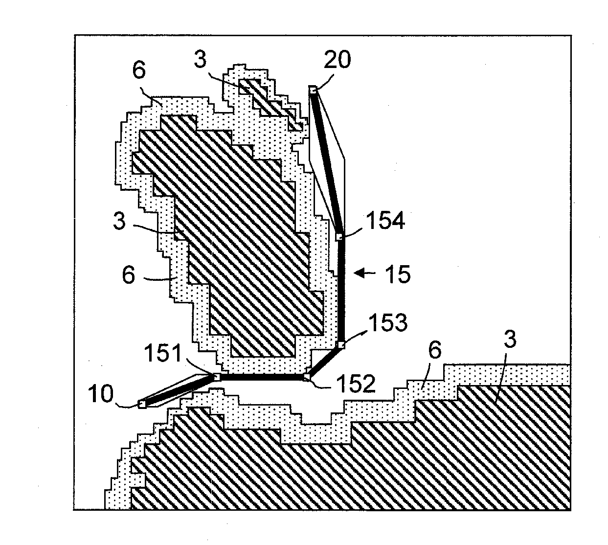
[0057]The method, which is to be described, of determining or plotting a horizontal air route profile that complies with the relief, regulated overfly zones and vertical flight and speed profiles prescribed on departure and / or on arrival, is based on the propagation distance transforms technique applied to air navigation, in a context of static constraints consisting of reliefs to be circumnavigated and regulated overfly zones to be complied with, and dynamic constraints consisting of a prescribed vertical flight and speed profile.

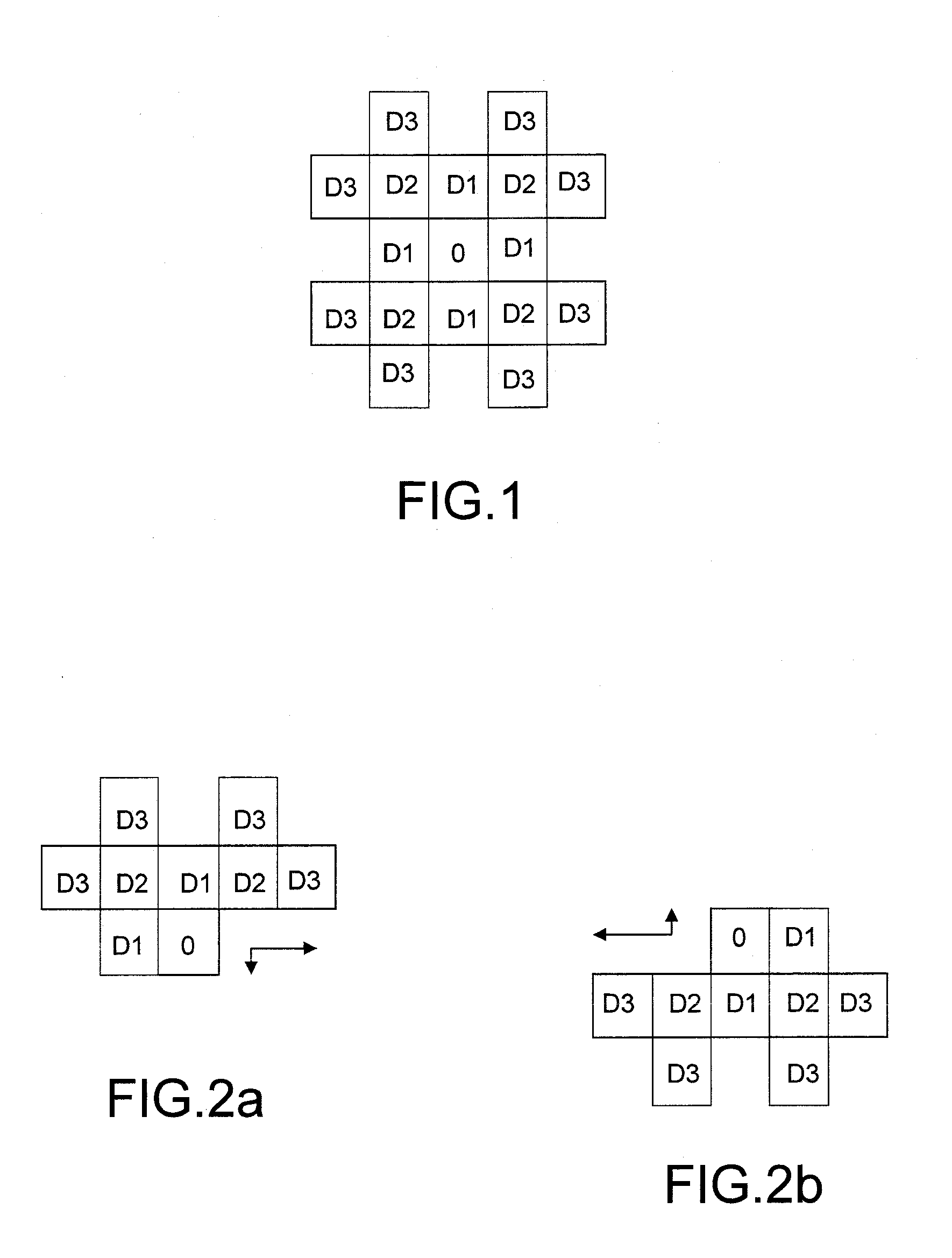
[0058]Propagation distance transforms first appeared in image analysis for estimating the distances between objects. These include chamfer mask distance transforms, examples of which are described by Gunilla Borgefors in an article entitled “Distance Transformation in Digital Images”, published in the review: Computer Vision, Graphics and Image Processing, vol. 34 pp. 344-378 in February 1986.

[0059]The distance between two points of a surface is the minimu...


PUM


Abstract

The present invention relates to the definition, in a flight plan, of the horizontal profile of an air route with vertical flight and speed profile prescribed on departure and/or on arrival, by a stringing together of check-points and/or turn points associated with local flight constraints and called “D-Fix” because they are not listed in a published navigation database like those called “Waypoints”. It consists in charting, on curvilinear distance maps, a direct curvilinear path joining the departure point to the destination point of the air route while complying with vertical flight and speed profiles prescribed on departure and/or on arrival and while guaranteeing a circumnavigation of the surrounding reliefs and compliance with regulated overfly zones, then in approximating the series of points of the direct curvilinear path by a sequence of straight segments complying with an arbitrary maximum deviation threshold relative to the points of the series and an arbitrary minimum lateral deviation threshold relative to the set of obstacles to be circumnavigated and in adopting as “D-Fix” points the points of the intermediate intersections of the rectilinear segments.

Description

CROSS-REFERENCE TO RELATED APPLICATIONS[0001]The present Application is based on International Application No. PCT / EP2006 / 068581, filed on Nov. 16, 2006, which in turn corresponds to French Application No. 05 12420, filed on Dec. 7, 2005, and priority is hereby claimed under 35 USC §119 based on these applications. Each of these applications are hereby incorporated by reference in their entirety into the present application.FIELD OF THE INVENTION[0002]The present invention relates to the definition, in a flight plan, of the horizontal profile of an air route with vertical flight and speed profile prescribed on departure and / or on arrival, by a stringing together of check-points and / or turn points associated with local flight constraints and called “D-Fix” (“Dynamic FIX”) because they are not listed in a published navigation database like those called “Waypoints”.BACKGROUND OF THE INVENTION[0003]The check- and / or turn points “Waypoints” listed in the published navigation databases co...

Claims


Application Information

Patent Timeline
IPC IPC(8): G08G5/04
CPCG01C21/00G08G5/0034
Inventor MARTY, NICOLASFRANCOIS, GILLESBITAR, ELIAS
Owner THALES SA
Why Eureka
Try Eureka