Modular wall plate for ganging commercial dimmers

a technology of commercial dimmers and modules, applied in the field of wall plates, can solve the problems of individual dimmers not being perfectly aligned with each other, wiring devices not being aligned, and heat sink bottom edges not being in perfect horizontal alignmen

Inactive Publication Date: 2009-08-18
PASS SEYMOUR
View PDF6 Cites 80 Cited by
  • Summary
  • Abstract
  • Description
  • Claims
  • Application Information

AI Technical Summary

Benefits of technology

[0011]The present invention addresses the needs described above by providing a modular wall plate system is needed that conveniently gangs dimmers of varying widths together in a multi-gang box in an aesthetically pleasing way.

Problems solved by technology

This gives rise to the problem that the wiring devices are not aligned to each other by the box.
However, the individual dimmers are usually not perfectly aligned with each other.
The edges of the heat sinks may be raised relative to each other, the side edges of the heat sink may not be vertically aligned with each other, and the bottom edges of the heat sink may not be in perfect horizontal alignment.
Because the individual dimmers are not perfectly aligned with each other in three-dimensional space, the wall plates will not be perfectly aligned either.
The wall plates will exhibit a stepped appearance that is both unacceptable and undesirable.
The edges of the individual wall plates look rough and non-uniform.
The drawbacks to this approach are the cost and lead time of having a custom wall plate manufactured.
Both of these factors are usually prohibitive.
As can be seen, an alignment issue arises whenever wiring devices of dissimilar width are installed in a multi-gang junction box.

Method used


Image

  • Modular wall plate for ganging commercial dimmers
  • Modular wall plate for ganging commercial dimmers
  • Modular wall plate for ganging commercial dimmers

Examples


first embodiment

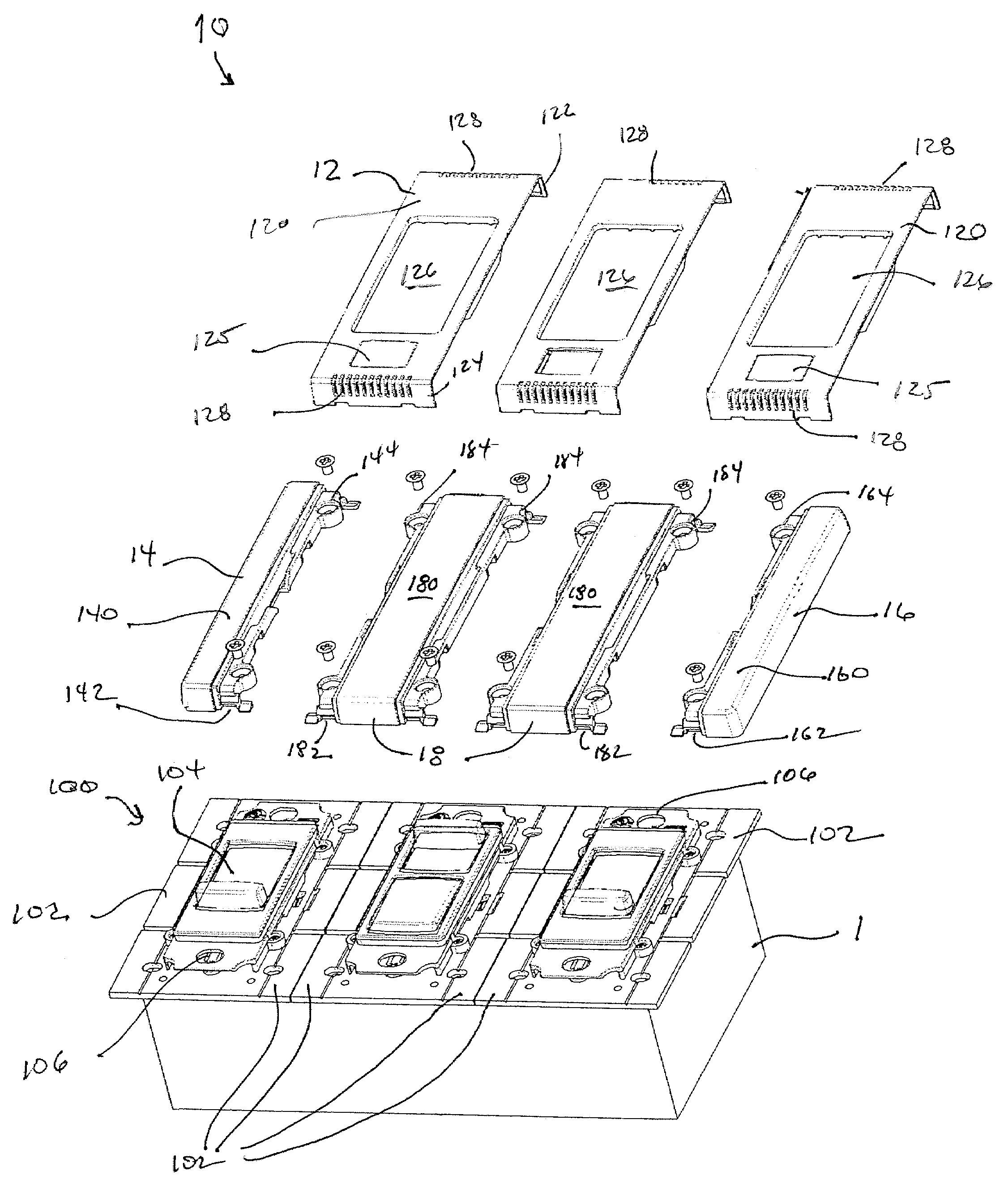
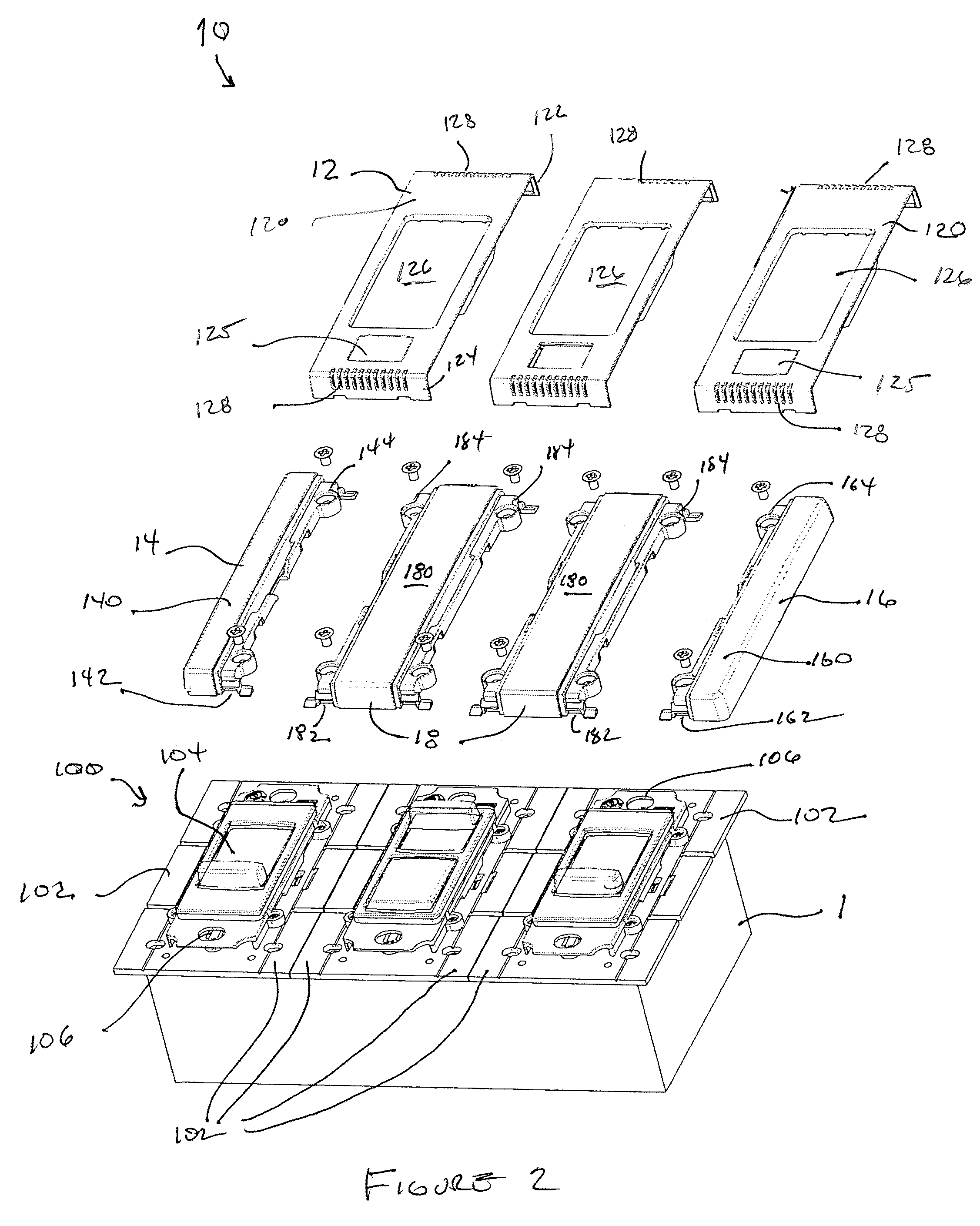
[0030]As embodied herein, and depicted in FIG. 2, an exploded view of a modular wall plate system 10 in accordance with the present invention is shown. Referring to FIG. 2, three dimmer wiring devices 100 are shown disposed in multi-ganged wall box 1. Each device 100 includes heat sink fins 102 disposed on either side of the device 100. Each device 100 also includes a user-accessible control feature 104 disposed on the device. The control feature may be a slide switch, a set switch, or any combination thereof. In other embodiments, the wiring devices 100 may include receptacles, protective devices, GFCIs, AFCIs, TVSS devices, lights, sensors, occupancy sensors, fan speed controllers, as well as dimmer devices. An individual device 100 may include more than one wiring device function, e.g. a dimmer and fan speed controller or a receptacle and a night light.

[0031]Reference is made to U.S. patent application Ser. No. 11 / 343,102, which is incorporated herein by reference as though fully...

second embodiment

[0040]As embodied herein and depicted in FIG. 6, an exploded view of a modular wall plate system in accordance with the present invention is disclosed. In this embodiment, three dimmer wiring devices 100 are again shown disposed in multi-ganged wall box 1. However, each interior heat sink fin, i.e., those that are not disposed at the edge of the wall box 1 are removed from the wiring devices 100.

[0041]The system includes a left-end cap 14 that is configured to be mounted over the heat sink 102 of the left most dimmer device shown in the FIG. 2. As before, left-end cap 14 includes a left-end cap finish surface 140 that is raised relative to the pair of recessed fastener holes 144 disposed on the right hand portion of the end cap. The pair of the recessed fastener holes 144 are configured to be mounted to the left-most edge of wiring device 100. A right-end cap 16 is configured to be mounted to an exterior heat sink portion of the right most wiring device shown in FIG. 2. The right-en...


PUM


Abstract

The present invention is directed to a modular wall plate system accommodating N-wiring devices within a wall box. N is an integer greater than or equal to one (1). The system includes a left-end cap configured to be mounted to an exterior portion of a left most wiring device of the N-wiring devices disposed in the wall box, the left-end cap including a left-end cap finish surface. A right-end cap is configured to be mounted to an exterior portion of a right most wiring device of the N-wiring devices disposed in the wall box, the right-end cap including a right-end cap finish surface. N-1 alignment couplers are disposed between each of the N-wiring devices. The N-1 alignment couplers are configured to align adjacent ones of the N-wiring devices at least in two-dimensions. Each of the N-1 alignment couplers includes a coupler finish surface. N-wall plates are configured to cover each of the N-wiring devices. Each of the N-wall plates includes a wall plate finish surface.

Description

BACKGROUND OF THE INVENTION[0001]1. Field of the Invention[0002]The present invention relates generally to wall plates for electrical wiring devices, and particularly to wall plates for commercial dimmers.[0003]2. Technical Background[0004]Multi-gang device boxes are configured to accommodate multiple wiring devices side by side. The multi-gang box includes several pairs of mounting tabs, each pair being separated from an adjacent pair of mounting tabs by a standard distance, such as 1.812 inches. This standard distance is commonly referred to as a “single-gang width.” Of course, each pair of mounting tabs includes a fastener aperture disposed in the top wall of the box and a corresponding fastener aperture disposed in the bottom wall of the box. The centerline passing through the top and bottom fastener holes of each pair is substantially parallel to the side walls of the box. Each device mounted in the multi-gang box is fastened to the top and bottom holes by inserting a fastener ...

Claims


Application Information

Patent Timeline
Patent Type & Authority Patents(United States)
IPC IPC(8): H02G3/14
CPCH02G3/14
Inventor SAVICKI, JR., GERALD R.
Owner PASS SEYMOUR
Why Eureka
Try Eureka