

Method for preventing backflow of resin in injection apparatus
a technology of injection apparatus and backflow, which is applied in the direction of auxillary shaping apparatus, ceramic shaping apparatus, manufacturing tools, etc., can solve the problems of affecting the product weight, the means are hardly adaptable to injection molding of low-viscosity resin, and the leakage of metering dispersion up to the valve closing, so as to improve the valve closing efficiency of low-viscosity material resin and eliminate the leakage
- Summary
- Abstract
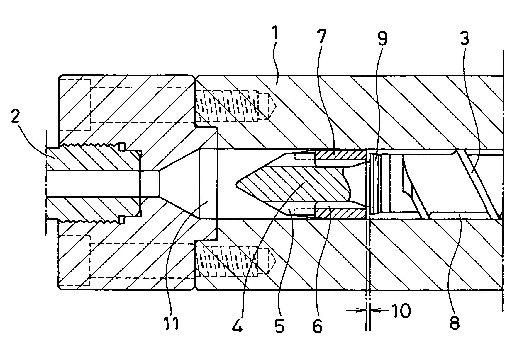
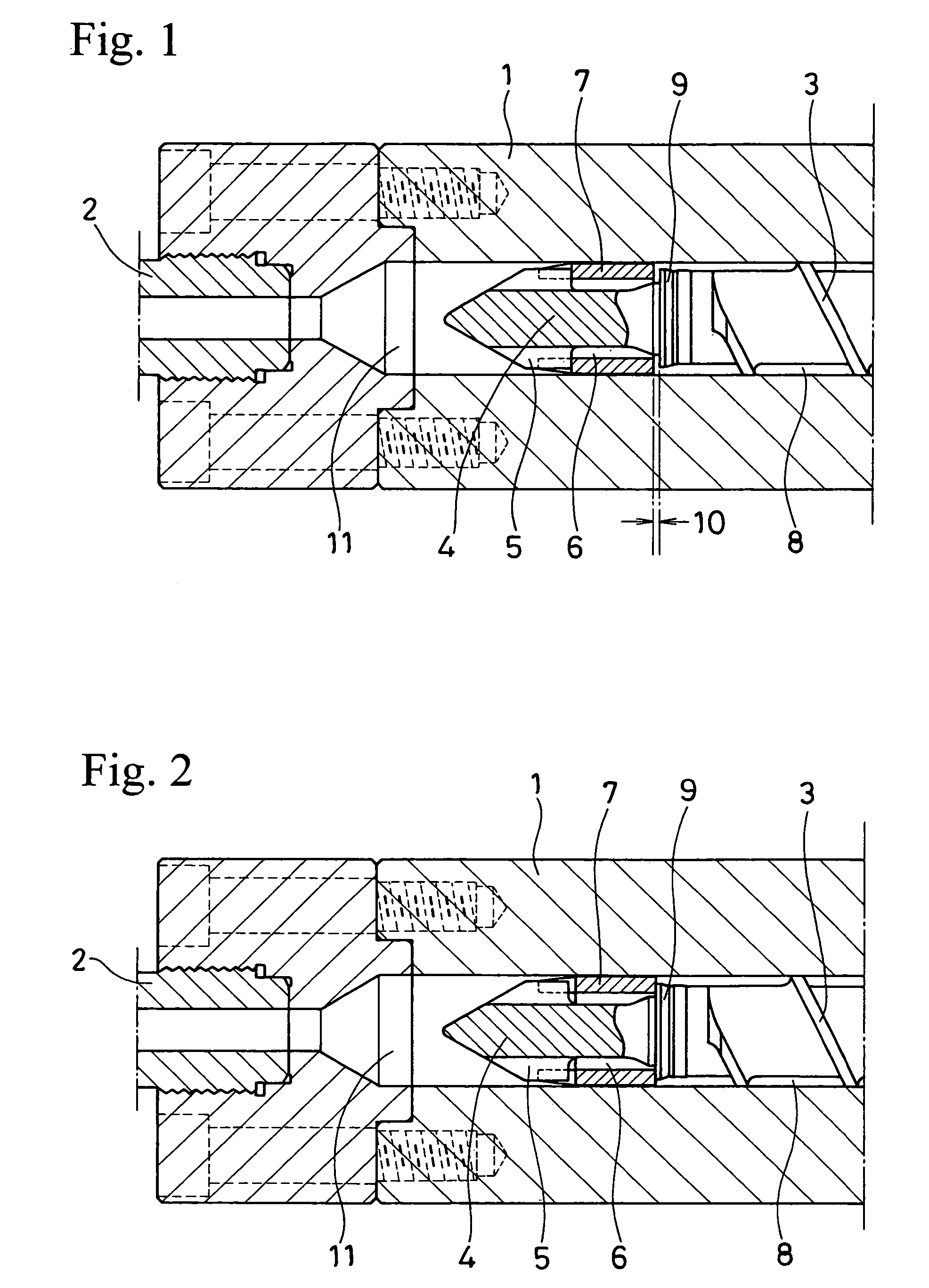
- Description
- Claims
- Application Information
AI Technical Summary
Benefits of technology
Problems solved by technology
Method used
Image

Examples
example
[0029]
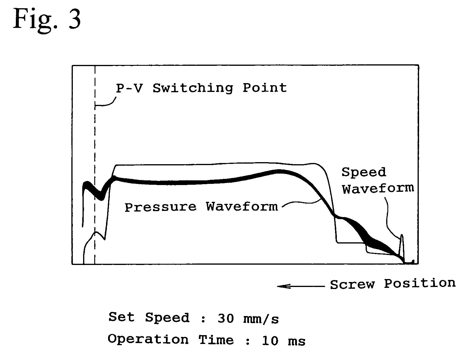
Material resin:Polycarbonate AD 55003 manufacturedby TEIJIN LTD.Viscosity (Pa · s):47Molding: Information15.5recording disk,Design weight (g):Injection moldingCD400E (manufactured by NISSEI PLASTICmachine:INDUSTRIAL CO.)Injection stroke (mm):30Flowing gap (mm):1.0Valve closing305070operation speed (mm / s):Operation time (ms):101010[No. 1]Injection filling speed (mm / s)V1 (initial speed)V2V3V4102010030[No. 2]Injection filling speed (mm / s)V1 (initial speed)V2V3V440404040
[0030]In Example No. 1, since the initial speed V1 of the injection filling speed is set to 10 mm / s, the valve closing operation speed to be set thereto is higher than the initial speed V1. In Example No. 2, since the initial speed V1 of the injection filling speed is set to 40 mm / s higher than that in No. 1, the valve closing operation speed 30 mm / s is to be set lower than the initial speed V1.
[0031]FIGS. 3 to 5 are monitoring charts of speed waveform and pressure waveform in valve closing operations with the abov...
PUM
| Property | Measurement | Unit |
|---|---|---|
| speed | aaaaa | aaaaa |
| speed | aaaaa | aaaaa |
| speed | aaaaa | aaaaa |
Abstract
Description
Claims
Application Information