Communications systems and methods

a communication system and optical data technology, applied in the field of wireless and wired optical data communication systems, can solve the problems of inter symbol interference (isi), increase in rate, etc., and achieve the effects of reducing the susceptibility of communicated data to systematic noise, reducing the susceptibility of communicated data, and reducing the sensitivity of the receiver

Inactive Publication Date: 2009-08-25
INTEL CORP
View PDF29 Cites 245 Cited by
  • Summary
  • Abstract
  • Description
  • Claims
  • Application Information

AI Technical Summary

Benefits of technology

[0007]Broadly speaking, embodiments of the above receiver facilitate substantial reduction in the effect of multipath reflections, either in free space or in a “wired” connection such as a passive optical network (PON) such as a network connecting a head end device to multiple (for example greater than 100, 500 or 1000) households. Embodiments of the above described receiver are also useful in mitigating the effects of pulse smearing which arise in multimode optical fibres. Depending upon the receiving system in which the receiver is used the pulse position data may comprise hard decision data or soft data, for example for a Viterbi or similar channel decoding system.
[0024]The above described techniques facilitate implementation of virtually a complete receiver system in a single integrated circuit, the integrated circuit including both a front end analogue-to-digital converter and subsequent digital received signal processing circuitry.

Problems solved by technology

There is interest in operating IrDA links at higher data rates but there are problems with the IrDA protocols when the data rates are increased significantly.
There are also general problems with infrared (and optical) data communications including interference, for example from fluorescent lights, and multipath dispersion, which can cause inter symbol interference (ISI).

Method used


Image

  • Communications systems and methods
  • Communications systems and methods
  • Communications systems and methods

Examples


Embodiment Construction

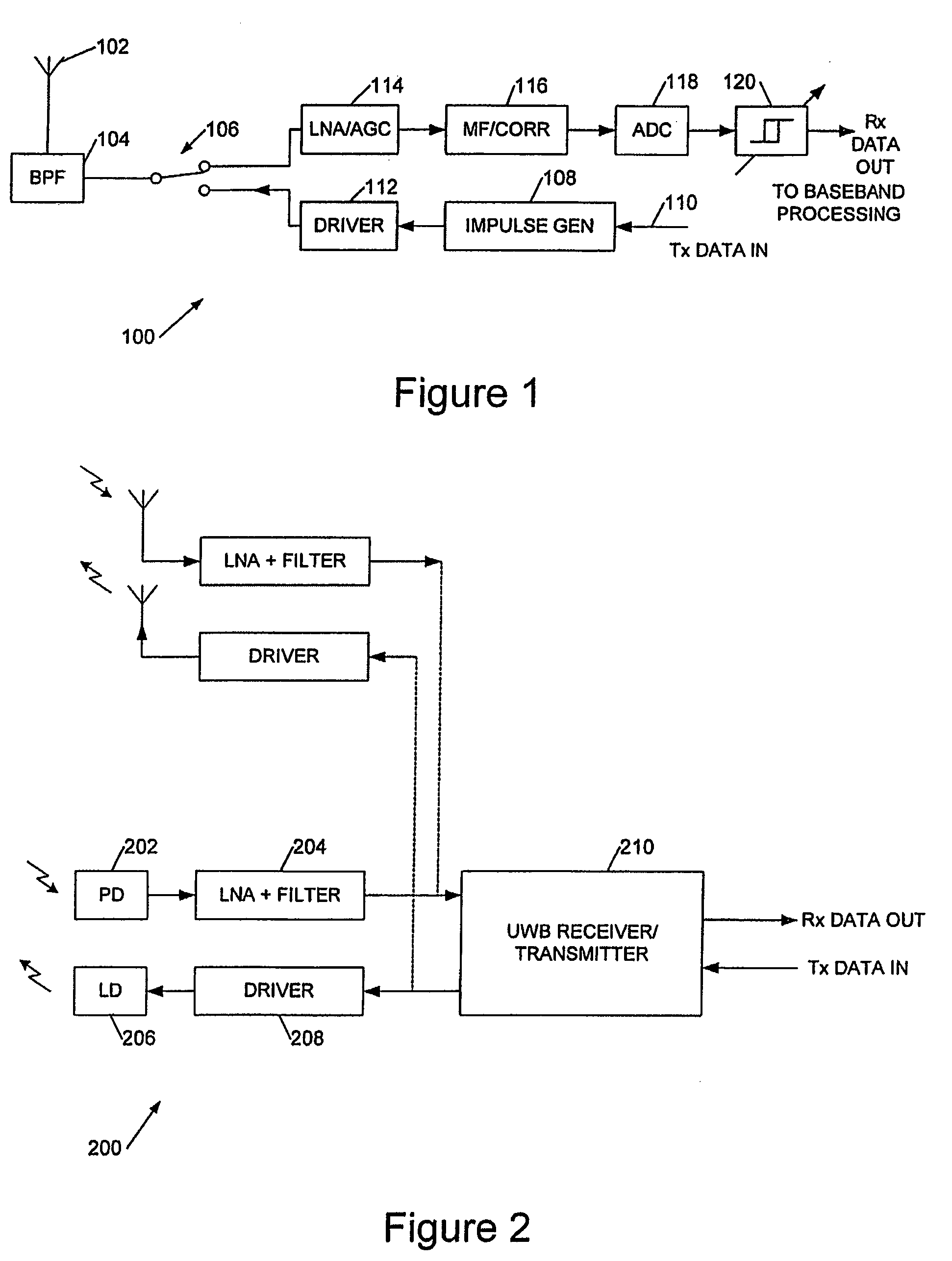
[0055]FIG. 1 shows an example of an analogue UWB transceiver 100. This comprises an transmit / receive antenna 102 with a characteristic impulse response indicated by bandpass filter (BPF) 104 (although in some instances a bandpass filter may be explicitly included), couples to a transmit / receive switch 106.

[0056]The transmit chain comprises an impulse generator 108 modulatable by a baseband transmit data input 110, and an antenna driver 112. The driver may be omitted since only a small output voltage swing is generally required. One of a number of modulation techniques may be employed, typically either OOK (on-off keying i.e. transmitting or not transmitting a pulse), M-ary amplitude shift keying (pulse amplitude modulation), or PPM (pulse position modulation i.e. dithering the pulse position). Typically the transmitted pulse has a duration of <1 ns and may have a bandwidth of the order of gigahertz.

[0057]The receive chain typically comprises a low noise amplifier (LNA) and automatic...


PUM


Abstract

This invention relates to systems and methods for wireless and wired optical data communications, in particular infrared data communications using techniques borrowed ultra wideband (UWB) radio.An optical data communications receiver for receiving data encoded using optical pulse position, the receiver comprising: an optical signal reception device; a reference signal memory for storing a reference channel response signal; and a correlator coupled to said reference signal memory and to said optical signal reception device for correlating a received optical pulse with said stored reference channel response signal to determine said optical pulse position; an output coupled to said correlator to provide pulse position data for said received optical pulse.

Description

BACKGROUND OF THE INVENTION[0001]1. Field of the Invention[0002]This invention relates to systems and methods for wireless and wired optical data communications, in particular infrared data communications using techniques borrowed ultra wideband (UWB) radio.[0003]2. Background Art[0004]Standards for infrared data communication are defined by the Infrared Data Association (IrDA: www.irda.org) and cover data communication rates to around 4 Mbps. The standards are generally directed to point-to-point connectivity at distances of up to 1 m. Using transceivers that broadcast infrared pulses in a cone of up to 30 degrees half angle off centre. The specifications also require that a maximum irradiance is not exceeded so as not to swamp and “blind” a receiver, for similar reasons the transmissions are half-duplex. The IrDA protocol stack bundles data for transmission into a data packets with start and stop bits, and, optionally, a CRC value. Over this runs a Link Access Protocol (LAP) for d...

Claims


Application Information

Patent Timeline
Patent Type & Authority Patents(United States)
IPC IPC(8): H04B10/06H04B10/40H04B10/66
CPCH04B10/66H04B10/40H04L1/004H04L25/4902
Inventor MOORE, MARK JUSTINLANG, JACK ARNOLD
Owner INTEL CORP
Why Eureka
Try Eureka