
Movable baffle columns for use with air handling units

a technology of air handling unit and baffle column, which is applied in the direction of lighting and heating apparatus, ventilation systems, heating types, etc., can solve the problems that the size of the ahu's footprint can have a direct impact on its cost and likelihood of being selected, and achieve the effect of small footprint and more economical

Active Publication Date: 2009-09-01
ENERGY LABS
View PDF14 Cites 20 Cited by
  • Summary
  • Abstract
  • Description
  • Claims
  • Application Information

AI Technical Summary

Benefits of technology

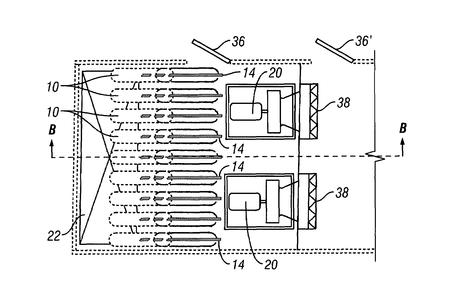
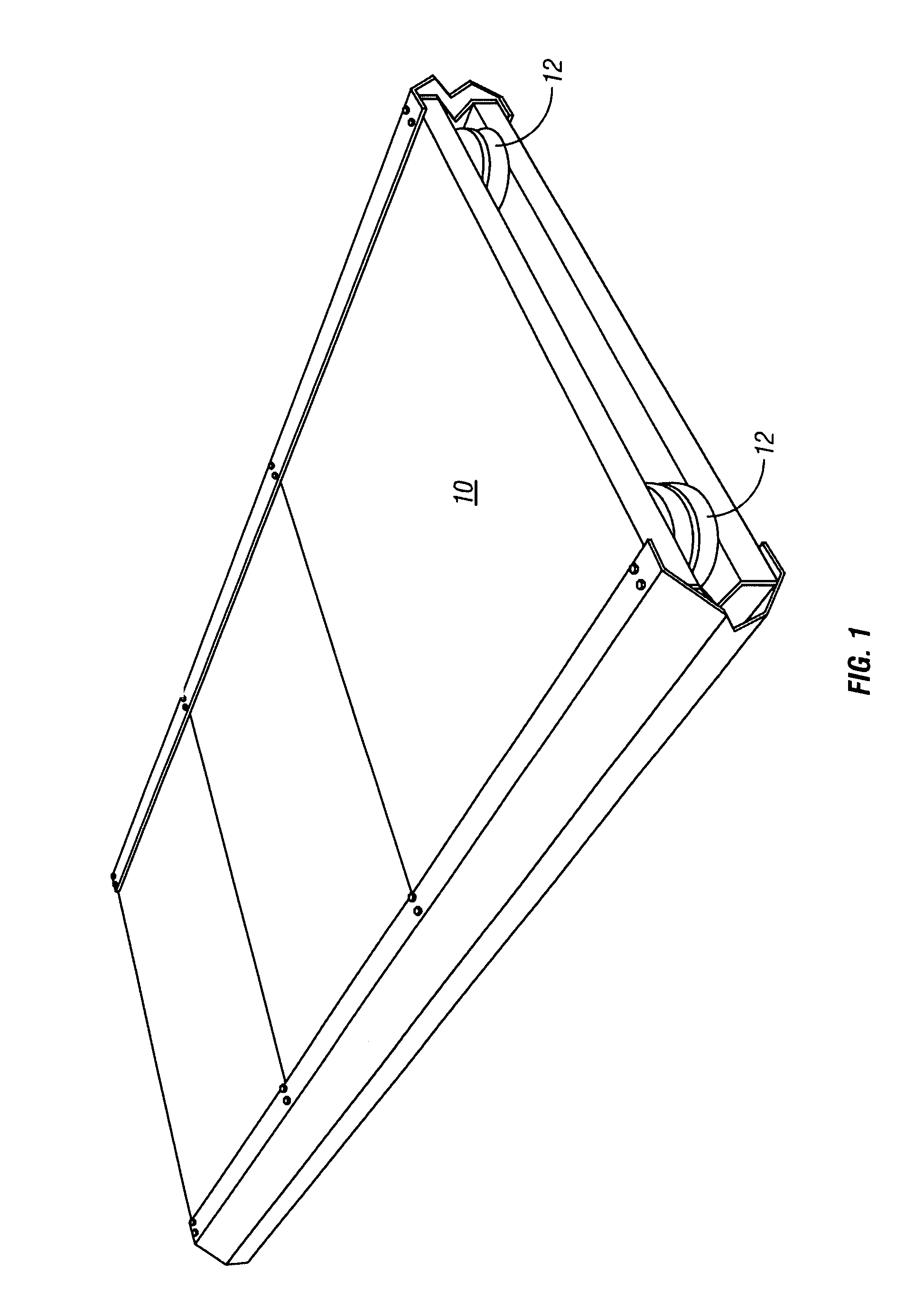
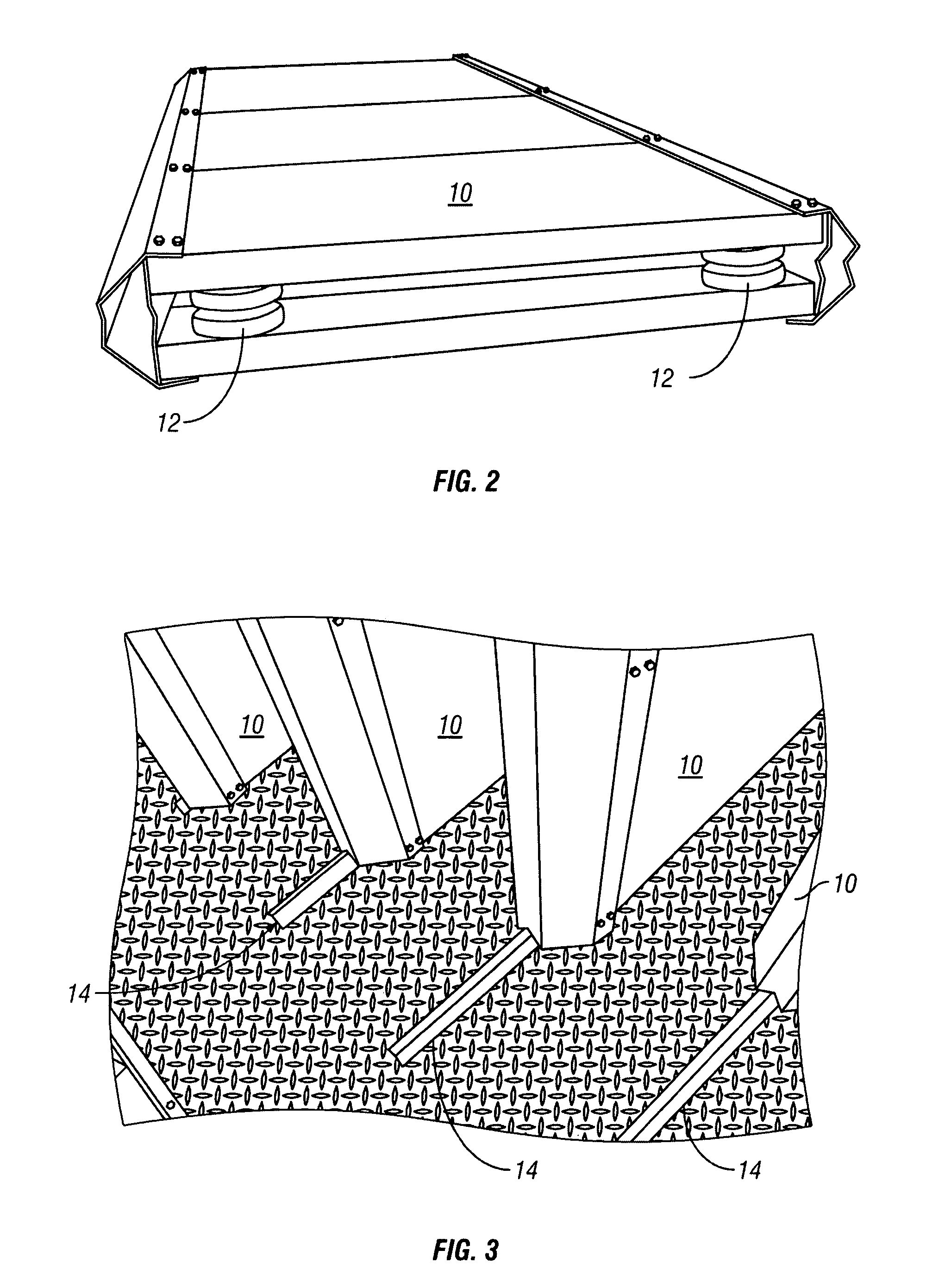
[0010]Movable baffle columns for use in conjunction with an air-handling unit. One or more baffle columns are mounted for rolling or sliding movement within the interior of the air handling unit housing. Each baffle column may be selectively moved between a use position proximate to a fan assembly, and a non-use position more distal from a fan assembly. The movable baffles permit the air-handling unit to be fabricated to fit within a smaller housing, and thus to have a smaller, more economical footprint.

Problems solved by technology

In the marketplace for heating, ventilation and air-conditioning (HVAC) systems where such custom AHUs are engineered and sold, the size of an AHU's footprint can have a direct impact on its cost and likelihood of being selected.

Method used


Image

  • Movable baffle columns for use with air handling units
  • Movable baffle columns for use with air handling units
  • Movable baffle columns for use with air handling units

Examples


Embodiment Construction

Best Modes for Carrying Out the Invention

[0020]The present disclosure is of an AHU apparatus having a reduced footprint without compromising AHU performance. By installing self-supporting sound-attenuating baffles on tracks, with complementary rollers or other means that permit translational movement, the presently disclosed apparatus permits the creation of temporary clearances that maintenance personnel need when an AHU is not operating. After maintenance completes its inspection and / or service, the baffles are returned to original, functional, positions prior to re-actuating the AHU.

[0021]A conventional wisdom that may have prevented the apparatus of the present disclosure from appearing in known AHU systems is that access sections between AHU components are considered to doubly function as regions where airflow can mix, concentrate or diffuse as the design intends. But these airflow considerations are relevant only when the AHU is in operation; so, the present apparatus exploits...


PUM


Abstract

A sound-baffling arrangement for use in conjunction with an air-handling unit. One or more sound baffle columns are mounted for rolling or sliding movement within the interior of the air handling unit housing. Each baffle column may be selectively moved between a use position proximate to the fan assemblies, and a non-use position more distal from the fan assemblies. The movable sound baffles permit the air-handling unit to be fabricated to fit within a smaller housing, and thus to have a smaller, more economical footprint.

Description

BACKGROUND OF THE INVENTION[0001]1. Field of the Invention (Technical Field)[0002]The present invention relates to air handling units, such as which move large volumes of air with motor-driven fans, and relates particularly to sound-attenuation components for such units, and specifically to movable sound attenuating baffles for air handling units.[0003]2. Background Art[0004]Custom air handling units (AHU) are mechanical equipment that deliver tempered and / or filtered air (via ductwork) to a building or portions of its interior space. FIGS. 5 and 7 of the drawing figures depict the general layout of an air handling unit conventional to the art. Because the one or more fans 20 contained within the AHU to move the air can be quite noisy, it is common to install a bank of passive sound-attenuating baffles 10 between the fan(s) 20 and the intake or discharge port (or both) of the AHU as needed. The baffles 10 may either be self-supporting members arranged parallel to each other, or an a...

Claims


Application Information

Patent Timeline
IPC IPC(8): E04F17/04
CPCF24F13/20F24F3/0442Y10S454/906
Inventor STORM, MARK
Owner ENERGY LABS
Learn More