Surface-mounted connector

a technology of surface mounting and connector, which is applied in the direction of fixed connections, coupling device connections, electric discharge lamps, etc., can solve the problems of large force required to fix the connector to the substrate, and achieve the effect of preventing the slippage of the fixing metal members, preventing the force required to insert the fixing metal members into the slots, and ensuring smooth mounting on the substra

Inactive Publication Date: 2009-09-01
YAZAKI CORP
View PDF4 Cites 2 Cited by
  • Summary
  • Abstract
  • Description
  • Claims
  • Application Information

AI Technical Summary

Benefits of technology

[0011]The invention is accomplished in the aforementioned view. An object of the invention is to provide a surface-mounted connector that can surely prevent the slip-off of a fixing metal member of a connector, which is inserted into a connector housing thereof from below, by simultaneously suppressing increase in the dimensions of the outer shape of the connector, and that can also assure a force for reliably and fixedly mounting the connector on a substrate.

Problems solved by technology

In addition, each of these conventional connectors has another problem in that because each of these conventional connectors has a structure in which each of the fixing metal members 102 and 123 is inserted into an associated one of the mounting portions 102 and 122 from above, the area of each of the substrate fixing portions 103a and 123b of the fixing metal members 103 and 123 cannot be increased, and that a large force for fixing the connector to the substrate cannot be obtained.

Method used


Image

  • Surface-mounted connector
  • Surface-mounted connector
  • Surface-mounted connector

Examples


Embodiment Construction

[0043]Hereinafter, preferred embodiments of the invention are described in detail with reference to the accompanying drawings.

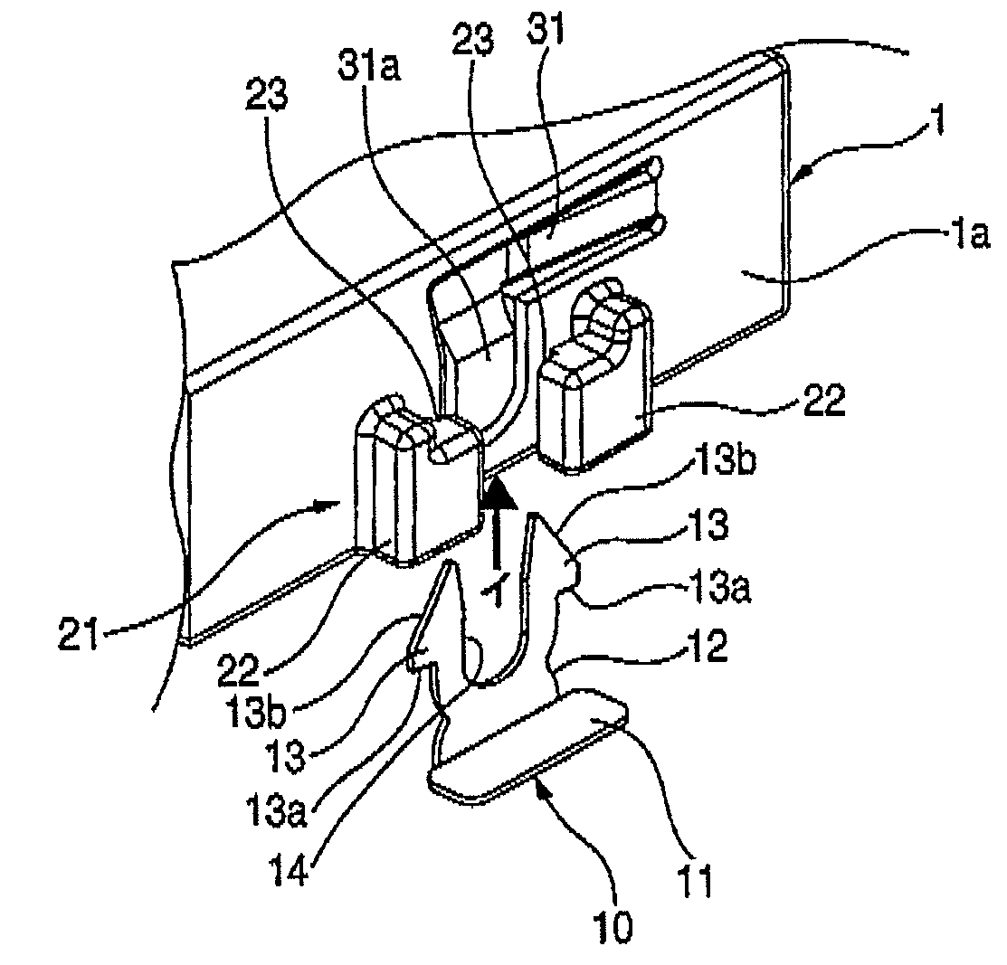
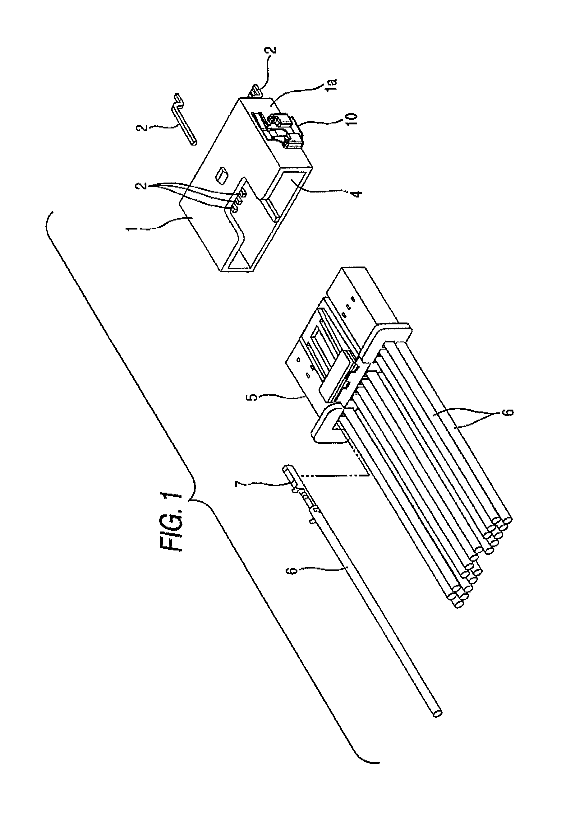
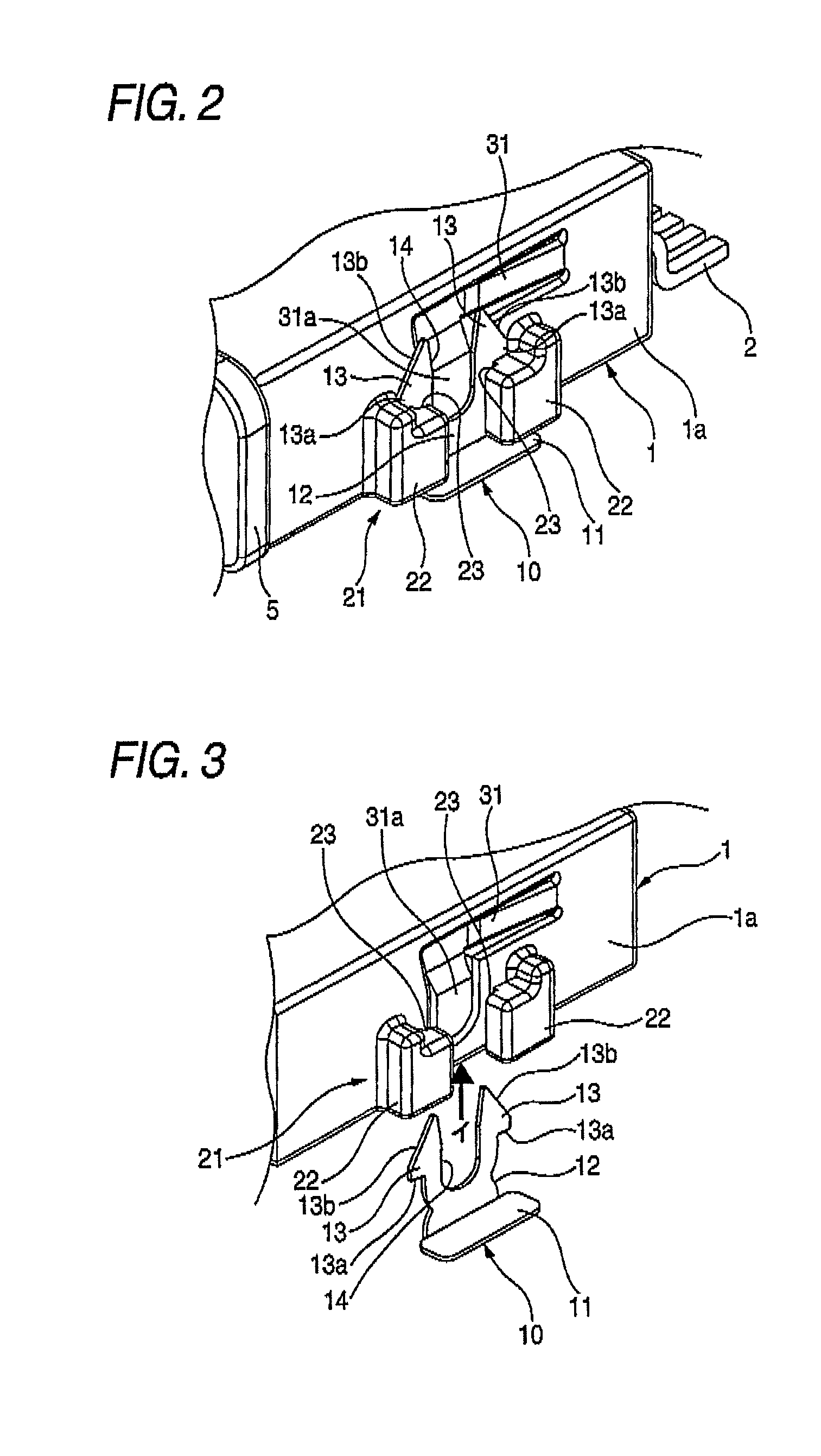
[0044]FIG. 1 is a perspective view illustrating a surface-mounted connector according to an embodiment of the invention and a connector to be connected thereto. FIG. 2 is a perspective view illustrating a place at which the surface-mounted connector illustrated in FIG. 1 is mounted on a substrate. FIG. 3 is a perspective view illustrating a structure for fixing the surface-mounted connector illustrated in FIG. 2 to the substrate. FIGS. 4A and 4B illustrate a fixing metal member to be inserted into a slot of the surface-mounted connector illustrated in FIG. 1. FIG. 4A is a perspective view, taken from a front side, illustrating this fixing metal member. FIG. 4B is a perspective view, taken from a rear side, illustrating this fixing metal member. FIG. 5 is a partially cross-sectional perspective view illustrating an engaging structure of the fixing metal member...


PUM


Abstract

A slot 21 is formed on each of both side walls of a connector housing 1. A housing attachment portion 12 of each fixing metal member 10 is inserted into and locked in an associated one of the slots 21. The housing attachment portion 12 is divided by a slit 14 formed in a central part thereof into both side arms 13, each of which has a hook 13a provided at the top thereof. Each of the arms 13 is inwardly bent when the associated hook passes through the slot. After the top of each of the arms 13 passes therethrough, each of the arms 13 is restored from the bent condition so as to engage the hooks 13a with the associated slot 21. An engaging projection portion 31a is provided in an inner wall of each of the slots 21 such that each of the engaging projection portions 31a is pushed out to the side of the associated slot 21 and fit into the slit 14 by inserting a mating connector 5 into a connecting concave portion 4 to thereby prevent the arms from being inwardly bent.

Description

BACKGROUND OF THE INVENTION[0001]1. Field of the Invention[0002]The present invention relates to a surface-mounted connector mounted on a substrate by soldering fixing metal members, which are respectively attached to both ends of a connector housing, to a substrate.[0003]2. Description of the Related Art[0004]FIG. 9 illustrates a conventional surface-mounted connector described in Patent Document 1. This surface-mounted connector has an insulating resin connector housing 101, which is formed like a substantially rectangular box and is put on a substrate 110, and fixing metal members 103 fixed to side walls of the connector housing 101 by being respectively press-fit into mounting portions 102 provided on outer surfaces of the side walls of the connector housing 101.[0005]Each of the fixing metal members 103 is formed by folding a strip-shaped metal plate cross-sectionally substantially like a letter “L”. Each of the fixing metal members 103 has a substrate fixing portion 103a to be...

Claims


Application Information

Patent Timeline
Patent Type & Authority Patents(United States)
IPC IPC(8): H01R13/60H01R12/57
CPCH01R12/725H01R12/707H01R13/6272
Inventor SAKAMOTO, NOBUYUKIZAITSU, KAZUKI
Owner YAZAKI CORP
Why Eureka
Try Eureka