Steering column device

a technology of steering column and rotor, which is applied in the direction of steering parts, vehicle components, transportation and packaging, etc., can solve the problems of difficult application of this technique and the same problems of structure, and achieve the effect of suppressing the reduction of the stiffness of the suspended portion

Inactive Publication Date: 2013-02-19
FUJI KIKO CO LTD
View PDF19 Cites 2 Cited by
  • Summary
  • Abstract
  • Description
  • Claims
  • Application Information

AI Technical Summary

Benefits of technology

[0012]It is also possible to enhance the section modulus of the mount bracket to ensure stiffness of the mount bracket by increasing a plate thickness of the mount bracket itself instead of providing the steel bracket 118 between the jacket bracket 113 and the mount bracket 114. However, this structure also bears the same problems as those described above due to an increase in the offset dimension from the shaft center of the steering shaft to the operating lever.
[0015]According to this aspect, the suspended portion of the mount bracket is fixed to the vehicle body by way of the fixation portion, and the surrounded portion surrounded by the first wall, the second wall, and the connecting portions is formed on the fixation portion. Hence, it is possible to increase the section modulus of the mount bracket and to sufficiently ensure stiffness of the mount bracket. Moreover, since a space is formed inside the suspended portion surrounded by the first wall, the second wall, and the connecting portions, it is possible to connect one end of the operating lever to the clamp bolt inside the suspended portion. In this way, it is possible to suppress an offset dimension from a shaft center of the steering shaft to the operating lever. Hence, this aspect is applicable even when there are vehicle structure restrictions that do not allow changes in the position of the operating lever and the vehicle mounting position, for example. Moreover, since the clamp bolt is relatively short, it is also possible to prevent the bolt from tilting or rattling in the unlocking action.
[0017]According to this configuration, when the mount bracket is attached to the vehicle body, the mount bracket is fixed to the vehicle body at two positions on respective right and left sides in the vehicle width direction. Moreover, an upper part of the suspended portion is fixed to the vehicle body. Hence, it is possible to enhance stiffness of the mount bracket or in particular to enhance stiffness of the suspended portion reliably, in a state where the mount bracket is attached to the vehicle body.
[0019]According to this configuration, the paired first protrusions protruding from the first wall of the suspended portion toward the jacket guide contact the paired second protrusions protruding from both ends in the lateral direction of the jacket toward the suspended portion at four positions in total. Hence, it is possible to lock the jacket guide onto the mount bracket stably and to enhance lock strength of the steering shaft.
[0021]According to this configuration, the lock mechanism configured to lock the jacket onto the mount bracket by using the clamp bolt is housed inside the suspended portion surrounded by the first wall, the second wall, and the connecting portions and the operating lever is allowed to protrude outward through the lever insertion hole formed at the lower side of the suspended portion. In this way, it is possible to dispose the operating lever at a position where an offset dimension from the shaft center of the steering shaft is relatively short.
[0023]According to this configuration, the second wall includes the opening opposed to the lock mechanism. Hence, it is possible to assemble the lock mechanism through this opening. Meanwhile, it is possible to suppress reduction in stiffness of the suspended portion by reinforcing the part around the opening of the second wall by use of the reinforcing rib.

Problems solved by technology

Accordingly, it is difficult to apply this technique if a position of the operating lever or a vehicle mounting position cannot be changed due to vehicle structure (layout) constraints.
However, this structure also bears the same problems as those described above due to an increase in the offset dimension from the shaft center of the steering shaft to the operating lever.

Method used


Image

  • Steering column device
  • Steering column device
  • Steering column device

Examples


second embodiment

[0052]Now, the present invention will be described below with reference to the accompanying drawings.

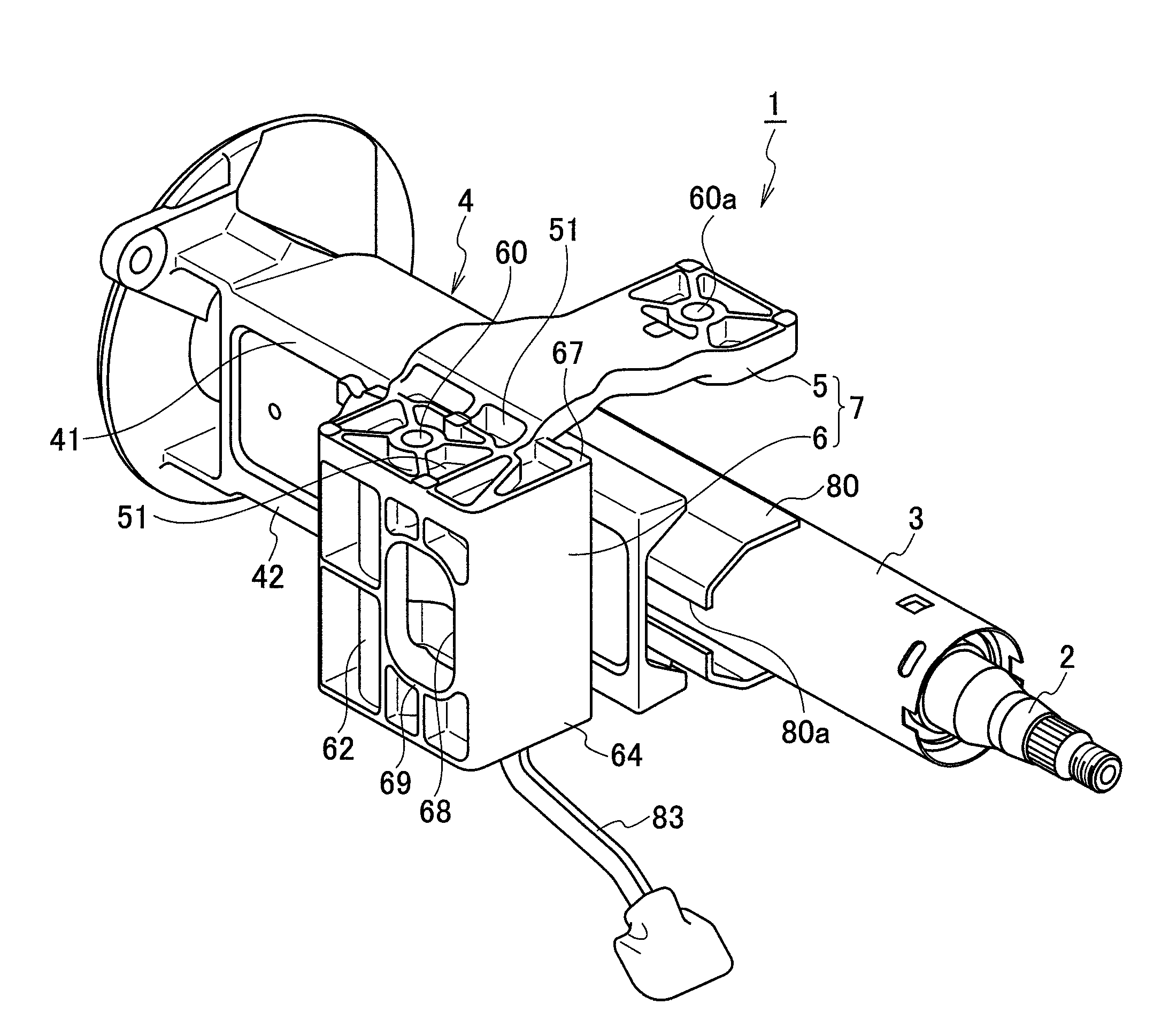
[0053]FIG. 9 is a perspective view of a mount bracket of the steering column device 1A according to the second embodiment of the present invention. Other features of the embodiment are similar to those described in the first embodiment and description thereof will be omitted. Moreover, a mount bracket 9 of the second embodiment includes a fixation portion 90 having a different configuration from that of the mount bracket 7 of the first embodiment. However, the configuration of the substantially box-shaped suspended portion 6 in the second embodiment is similar to that in the first embodiment.

first embodiment

[0054]The fixation portion 90 is formed substantially into a plate shape and includes attachment holes (attachment portions) 91 and 91a located at two positions right and left in the vehicle width direction. One of the attachment holes 91 is located on a surrounded portion 92 of the fixation portion 90 surrounded by the first wall 61, the second wall 62, the front side wall 63, and the rear side wall 64. While the attachment holes 60 and 60a are provided so as to stride over the jacket 3 in the first embodiment, the fixation portion 90 is formed in this embodiment such that the other attachment hole 91a is located on an opposite side of the jacket 3 beyond the suspended portion 6.

[0055]This embodiment is effective in a case where it is not possible to ensure a space above the jacket 3 when attached to the vehicle, for example.

[0056]The first and second embodiments exemplifies the case where the mount bracket 7 includes the fixation portion 5, 90 and the suspended portion 6, which ar...


PUM


Abstract

A steering column device includes a mount bracket including a suspended portion hanging from a fixation portion. The suspended portion includes: a first wall extending along and adjacent to the jacket guide, a second wall located on an outside of the first wall in a vehicle width direction; and a front side wall and a rear side wall connecting front ends and rear ends of the first wall and the second wall to each other. Operation of an operating lever protruding from the suspended portion tightens a clamp bolt to connect and fix the jacket to the mount bracket.

Description

CROSS REFERENCE TO RELATED APPLICATION[0001]This application is based upon and claims the benefit of priority from the prior Japanese Patent Application No. 2010-042904, filed on Feb. 26, 2010, the entire contents of which are incorporated herein by reference.BACKGROUND OF THE INVENTION[0002]1. Field of the Invention[0003]The present invention relates to a steering column device provided with a jacket supporting a steering shaft rotatably.[0004]2. Description of the Related Art[0005]Japanese Unexamined Patent Application Publication No. 2002-46623 and Published Japanese Translation of PCT International Publication No. 2005-525958 disclose steering column devices of the related art, each of which includes a jacket supporting a steering shaft rotatably, a jacket guide configured to guide the jacket, and a lock mechanism configured to lock the jacket by tightening a clamp bolt.[0006]As shown in FIG. 1, a steering column device 100 disclosed in Japanese Unexamined Patent Application Pub...

Claims


Application Information

Patent Timeline
Patent Type & Authority Patents(United States)
IPC IPC(8): B62D1/185B62D1/16B62D1/184B62D1/18
CPCB62D1/184B62D1/11B62D1/16
Inventor WARASHINA, TOSHIHIKOUESAKA, YOTA
Owner FUJI KIKO CO LTD
Why Eureka
Try Eureka