Aluminum alloy propeller shaft and friction welding process thereof

a technology of aluminum alloy and propeller shaft, which is applied in the direction of manufacturing tools, couplings, transportation and packaging, etc., can solve the problems of reducing the mechanical strength of the base metal of aluminum alloy material, deteriorating the overall length accuracy deteriorating so as to achieve the effect of suppressing the variation in the length dimension of the aluminum alloy propeller shaft and enhancing the yield of the propeller sha

Active Publication Date: 2015-04-14
HITACHI ASTEMO LTD
View PDF3 Cites 2 Cited by
  • Summary
  • Abstract
  • Description
  • Claims
  • Application Information

AI Technical Summary

Benefits of technology

[0009]The present invention has been made in view of the above-described problem in the conventional friction welding process. An object of the present invention is to provide an aluminum alloy propeller shaft capable of effectively suppressing variation in dimension of the overall length and a friction welding process of the propeller shaft.
[0024]The present invention can attain an effect of effectively suppressing variation in length dimension of an aluminum alloy propeller shaft and enhancing a yield of the propeller shaft.

Problems solved by technology

In addition, if an amount of the heat input is large, the aluminum alloy material is heat-softened to cause reduction of a mechanical strength of the base metal of the aluminum alloy material.
Further, since an upset distance variation rate of the aluminum alloy material is large, there is a fear that a change in value of the upset distance is caused due to variation in upset pressure timing, thereby deteriorating an accuracy in dimension of an overall length of the propeller shaft.
As a result, as described above, particularly, variation in overall length dimension of the propeller shaft will be readily caused to thereby cause a technological problem such as deterioration of a yield of the propeller shaft.

Method used


Image

  • Aluminum alloy propeller shaft and friction welding process thereof
  • Aluminum alloy propeller shaft and friction welding process thereof
  • Aluminum alloy propeller shaft and friction welding process thereof

Examples


experiment 2

[0062]Experiment 2 in which the position control (LA control) according to the embodiment of the present invention was carried out as follows. As indicated by solid line in FIG. 4, after application of the friction pressure P1 was started from the time at which the contact of the workpieces was carried out, current positions of the butting portions of tube 1 and yoke members 2, 3 in the axial direction thereof were detected. At a time at which actual upset distances of tube 1 and yoke members 2, 3 reached predetermined value LA, the main shaft rotation stop command signal was outputted, and at the same time, an upset pressure command signal was outputted to apply upset pressure P2. Then, the application of the upset pressure P2 was continued until a predetermined time has elapsed after the rotation of the main shaft was completely stopped.

experiment 3

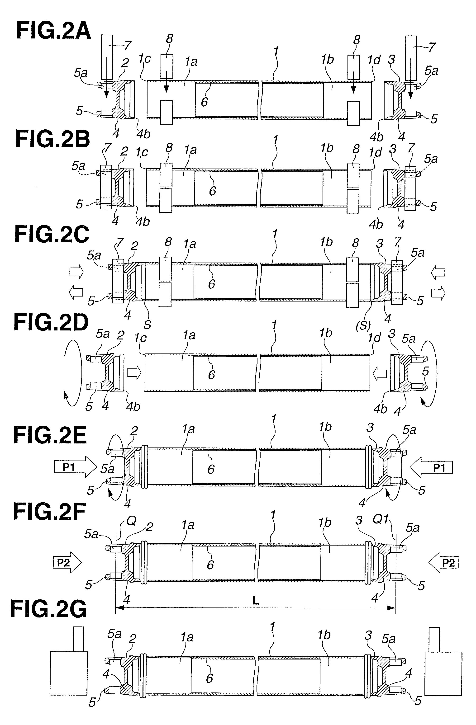
[0063]Experiment 3 in which the combination of the LA control and the F2θ control according to the embodiment of the present invention as shown in FIG. 2A to FIG. 2G was carried out as follows. FIG. 5 shows a relationship between control timing and parameters such as pressure, upset distance, preheat pressure, and rotation speed of yoke members 2, 3 which was obtained in Experiment 3. Similar to Experiment 2, after application of the friction pressure P1 was started from the time at which the contact of the workpieces was carried out, current positions of the butting portions of tube 1 and yoke members 2, 3 in the axial direction thereof were detected. At the time at which actual upset distances of tube 1 and yoke members 2, 3 reached the predetermined value LA, the main shaft rotation stop command signal was outputted.

[0064]After that, when rotation angle F2θ before the rotation of the main shaft was completely stopped had fallen in a predetermined range, the upset pressure command...


PUM

PropertyMeasurementUnit
thicknessaaaaaaaaaa
lengthaaaaaaaaaa
outer diameteraaaaaaaaaa

Abstract

An aluminum alloy propeller shaft including a tube made of an aluminum alloy, and a pair of yoke members made of an aluminum alloy, the yoke members including cylindrical base portions friction-welded to opposite end portions of the tube, each of the yoke members including a tip end portion having a pair of bearing retaining holes aligned with each other in a radial direction of the base portion. Variation in length between a central axis of the bearing retaining holes in one of the yoke members and a central axis of the bearing retaining holes in the other yoke member with respect to a reference length is set within a range of from +2.0 mm to −2.0 mm. A friction welding process of producing an aluminum alloy propeller shaft, including a friction step, a position displacement detection step, a rotation stop step and an upset step.

Description

BACKGROUND OF THE INVENTION[0001]The present invention relates to an aluminum alloy propeller shaft as a power transmission device for a vehicle, and a friction welding process of the propeller shaft.[0002]As is generally known, a method of bonding a tube of a vehicular propeller shaft and a yoke member to each other includes a friction welding process with high accuracy in addition to MIG or TIG welding.[0003]In the friction welding process, a yoke member as one member is brought into friction contact with each of opposite ends of a tube as the other fixed member while being rotated through a main shaft. Then, in a preheat step, the members are pressed onto each other at a predetermined preheat pressure to thereby cause a temperature rise thereof up to a predetermined temperature value in order to obtain an amount of heat necessary for pressure welding the members. Subsequently, a rotation number and a friction pressure of the main shaft are set at predetermined values to heat a bo...

Claims


Application Information

Patent Timeline
Patent Type & Authority Patents(United States)
IPC IPC(8): F16C3/02B23K20/12B23K20/233
CPCF16C3/02B23K20/121F16C3/023B23K20/12B23K20/2336B23K2203/10B23K20/122F16C2326/06F16C2226/36F16D1/027F16D3/387B23K2103/10B23K20/123B23K20/129B60K17/24C22C21/06
Inventor YOSHIDA, KEIGOMATSUMOTO, KAZUYA
Owner HITACHI ASTEMO LTD
Why Eureka
Try Eureka