
Electric power supply system

a technology of electric power supply system and power supply system, which is applied in the direction of dc-ac conversion without reverse, special data processing applications, and electric energy management. it can solve the problem of shortening the electric power of commercial electric power system

Active Publication Date: 2009-09-01
TOYOTA JIDOSHA KK
View PDF18 Cites 43 Cited by
  • Summary
  • Abstract
  • Description
  • Claims
  • Application Information

AI Technical Summary

Benefits of technology

Enables the use of vehicles to supplement commercial electric power during shortages, optimizing power supply and reducing communication costs by integrating vehicle power generation into the existing infrastructure.

Problems solved by technology

Japanese Patent Laying-Open No. 04-295202, however, does not particularly consider an electric power supply system that provides a reverse flow of its generated AC power to a commercial electric power system and that totally manages electric power supply from a plurality of vehicles connected to the commercial electric power system.

Method used


Image

  • Electric power supply system
  • Electric power supply system
  • Electric power supply system

Examples


Embodiment Construction

[0027]Embodiments of the present invention are hereinafter described in detail with reference to the drawings. It is noted that like or corresponding components are denoted by like reference characters and a description thereof is not repeated.

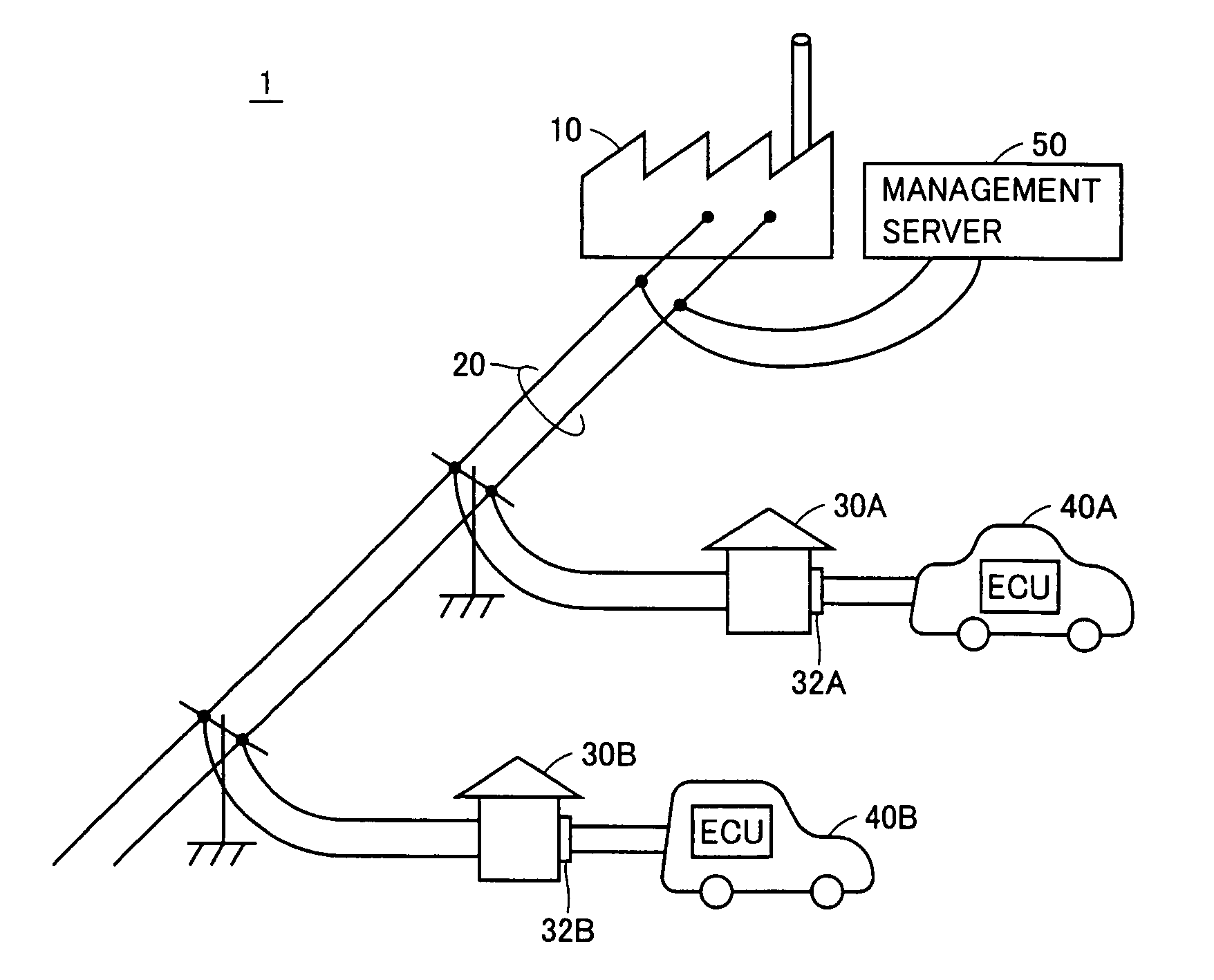
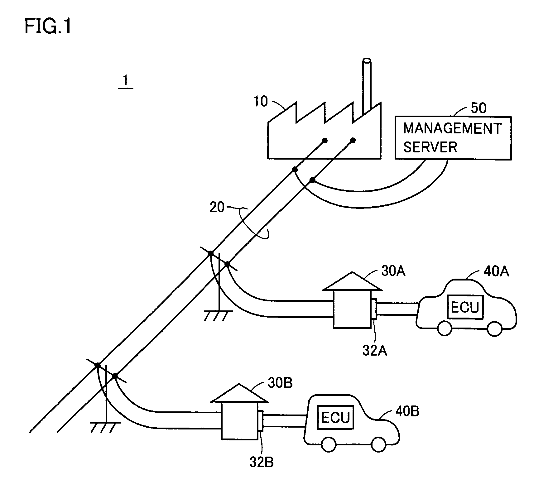
[0028]FIG. 1 is an entire block diagram of an electric power supply system according to an embodiment of the present invention. Referring to FIG. 1, this electric power supply system 1 includes a power station 10, a power transmission line 20, houses 30A, 30B, vehicles 40A, 40B, and a management server 50.

[0029]Power station 10 generates commercial electric power to output the generated commercial electric power to power transmission line 20. Houses 30A, 30B are connected to power transmission line 20 to receive the commercial electric power as supplied from power transmission line 20. Further, houses 30A, 30B receive, from vehicles 40A, 40B respectively, commercial electric power generated by vehicles 40A, 40B, and output the commercial elect...


PUM

PropertyMeasurementUnit
electric poweraaaaaaaaaa
AC poweraaaaaaaaaa
power-supply capabilityaaaaaaaaaa

Abstract

Vehicles are connected to respective receptacles of houses and are capable of generating commercial AC power to supply the generated electric power to a power transmission line. The vehicles communicate with a management server via the houses and the power transmission line. The vehicles output to the management server such information items concerning the vehicles as vehicle ID, amount of generated electric power and remaining amount of fuel. When electric power shortage occurs, the management server generates a start command and a power generation command for the vehicles based on the information concerning the vehicles to output the generated commands to the vehicles.

Description

TECHNICAL FIELD[0001]The present invention relates to an electric power supply system. In particular, the invention relates to an electric power supply system that uses a vehicle capable of generating commercial AC power and supplying the generated commercial AC power to the outside of the vehicle.BACKGROUND ART[0002]Japanese Patent Laying-Open No. 04-295202 discloses an electric motor drive and power processing apparatus used in electrically powered vehicles. The electric motor drive and power processing system includes a secondary battery, inverters IA, IB, induction motors MA, MB, and a control unit. Induction motors MA, MB include respective windings CA, CB in a Y configuration, and windings CA, CB have neutral nodes NA, NB connected via an EMI filter to an input / output port.[0003]Inverters IA, IB are provided correspondingly to induction motors MA, MB respectively and connected respectively to windings CA, CB. Further, inverters IA, IB are connected in parallel with the seconda...

Claims


Application Information

Patent Timeline
Patent Type & Authority Patents(United States)
IPC IPC(8): F02B63/04G06F17/00H01M8/00H02J7/00H02J3/38H02J3/46H02M7/48
CPCB60K6/46B60L11/1842B60W10/08H02J7/1423H02J13/0024B60L11/18B60L2210/20B60W20/00B60W2560/02H02J3/38Y02B90/2623Y02E60/721Y02T10/6217Y02T10/7005Y02T10/725Y02T90/16Y04S10/126Y04S40/122Y02T90/14Y04S30/12B60L53/14B60L50/62B60L50/16B60L55/00B60L58/40B60L53/68H02J13/00009B60W2530/209Y02E60/00Y02T10/62Y02T10/7072Y02T10/72Y02T90/12Y02T90/167Y04S40/121Y02T10/70Y02B90/20Y02T90/40
Inventor OYOBE, HICHIROSAIISHIKAWA, TETSUHIROMINEZAWA, YUKIHIRO
Owner TOYOTA JIDOSHA KK
Learn More