Dielectric resonators with axial gaps and circuits with such dielectric resonators

a dielectric resonator and axial gap technology, applied in the direction of resonators, basic electric elements, waveguide devices, etc., can solve the problems of huge problems, extremely difficult to tune such filters and other circuits, and essentially impossible to build effective dielectric resonator circuits, etc., to improve mode separation and spurious response, improve the effect of dielectric resonator circuits and easy tuning

Inactive Publication Date: 2009-09-01
COBHAM ADVANCED ELECTRONICS SOLUTIONS
View PDF71 Cites 0 Cited by
  • Summary
  • Abstract
  • Description
  • Claims
  • Application Information

AI Technical Summary

Benefits of technology

[0014]It is a further object of the present invention to provide dielectric resonator circuits with improved mode separation and spurious response.
[0015]It is one more object of the present invention to provide dielectric resonator circuits that are easy to tune.
[0016]In accordance with principles of the present invention, a dielectric resonator is provided with an air (or other dielectric) gap axially interrupting the body of the resonator. Preferably, the resonator body is conical or a stepped cylinder. However, the invention is equally workable with a straight-sided cylindrical resonator body. Filters and other dielectric resonator circuits can be built using such resonators that will have improved spurious response and be more easily tunable.

Problems solved by technology

However, it is essentially impossible to build an effective dielectric resonator circuit with dielectric resonators having a dielectric constant greater than about 45.
Specifically, as the dielectric constant increases above about 45, it becomes extremely difficult to tune such filters and other circuits because of the strong field concentrations in and around the dielectric resonators (mostly inside the dielectric resonators, but with some field outside).
Spurious response, in particular, becomes a huge problem in connection with low frequency circuits, e.g., 800 MHz and lower).
Poor spurious response is particularly a problem with respect to lower frequency applications because the dielectric resonators at lower frequencies must be physically larger.
Typically, all of the modes other than the fundamental mode, e.g., the TE mode, are undesired and constitute interference.
The H11 mode, however, typically is the only interference mode of significant concern.
However, the TM mode sometimes also can interfere with the TE mode, particularly during tuning of dielectric resonator circuits.
The H11 mode and the TM mode, however, can be rather close in frequency to the TE mode and thus can be difficult to separate from the TE mode in operation.
Accordingly, not only must the enclosure usually be constructed of a conductive material, but also it must be very precisely machined to achieve the desired center frequency performance, thus adding complexity and expense to the fabrication of the system.

Method used


Image

  • Dielectric resonators with axial gaps and circuits with such dielectric resonators
  • Dielectric resonators with axial gaps and circuits with such dielectric resonators
  • Dielectric resonators with axial gaps and circuits with such dielectric resonators

Examples


Embodiment Construction

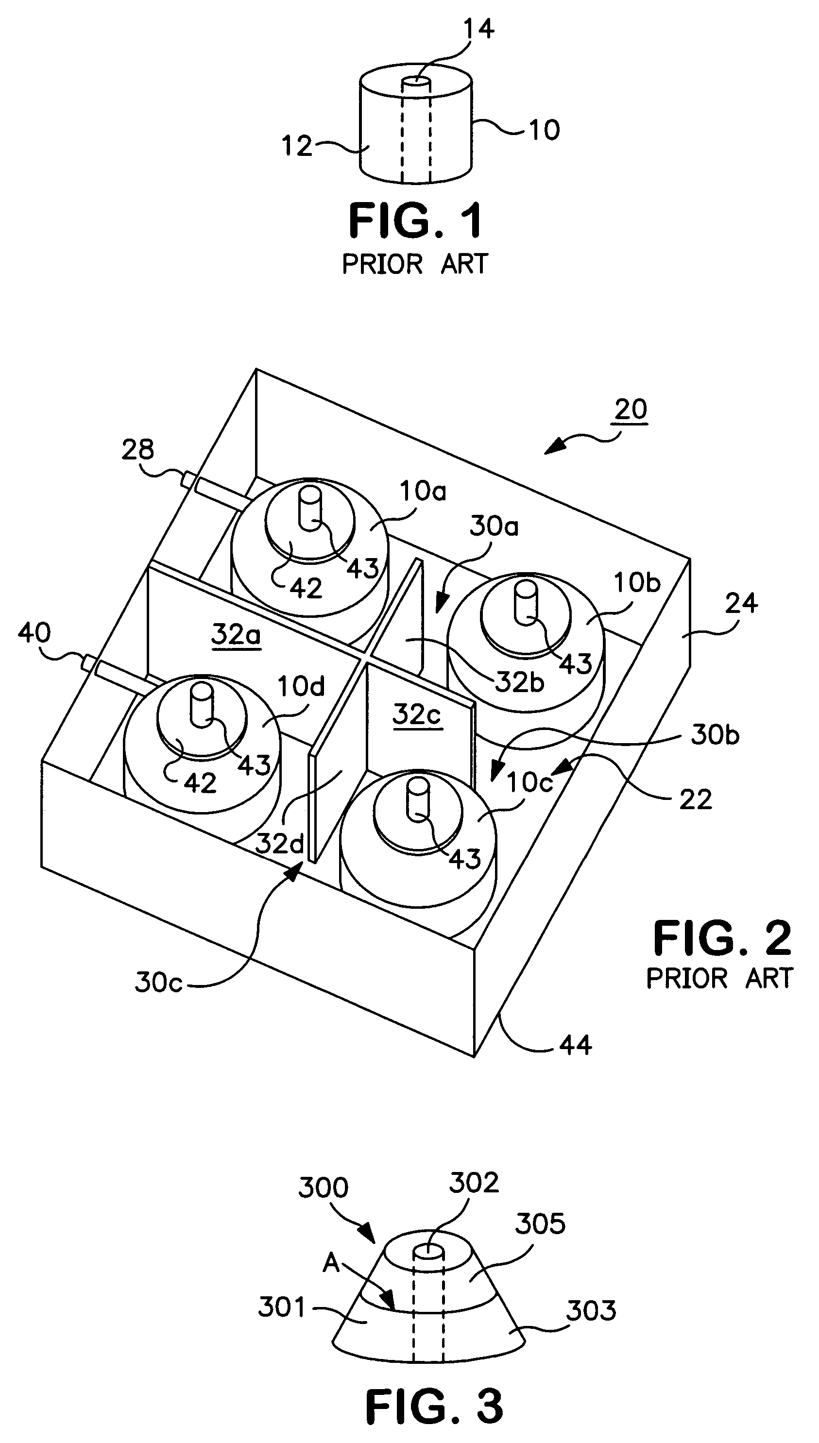
[0025]U.S. Patent Publication No. 2004 / 0051602, which is fully incorporated herein by reference, discloses new dielectric resonators as well as circuits using such resonators. One of the primary advantages of the new resonators disclosed in the aforementioned patent application is that the field strength of the TE mode field outside of and adjacent the resonator varies along the longitudinal dimension of the resonator. A key feature of these new resonators that helps achieve this goal is that the cross-sectional area of the resonator measured parallel to the field lines of the TE mode varies along the axial direction of the resonator, i.e., perpendicularly to the TE mode field lines. In one embodiment, the cross-section varies monotonically as a function of the longitudinal dimension of the resonator, i.e., the cross-section of the resonator changes in only one direction (or remains the same) as a function of height. In one preferred embodiment, the resonator is conical, as discusse...


PUM


Abstract

A dielectric resonator with an air (or other dielectric) gap axially interrupting the body of the resonator and circuits employing such resonators. Preferably, the resonator body is conical or a stepped cylinder. However, the invention also is workable with a straight-sided cylindrical resonator body.

Description

FIELD OF THE INVENTION[0001]The invention pertains to dielectric resonators, such as those used in microwave circuits for concentrating electric fields, and to the circuits made from them, such as microwave filters.BACKGROUND OF THE INVENTION[0002]Dielectric resonators are used in many circuits, particularly microwave circuits, for concentrating electric fields. They can be used to form filters, oscillators, triplexers, and other circuits. The higher the dielectric constant of the dielectric material from which the resonator is formed, the smaller the space within which the electric fields are concentrated. Suitable dielectric materials for fabricating dielectric resonators are available today with dielectric constants ranging from approximately 10 to approximately 150 (relative to air). These dielectric materials generally have a mu (magnetic constant, often represented as μ) of 1, i.e., they are transparent to magnetic fields.[0003]However, it is essentially impossible to build an...

Claims


Application Information

Patent Timeline
Patent Type & Authority Patents(United States)
IPC IPC(8): H01P1/20H01P7/10
CPCH01P1/2084
Inventor PANCE, KRISTI DHIMITERHEBERT, RONALD FRANCISSCHWAB, PAUL JOHN
Owner COBHAM ADVANCED ELECTRONICS SOLUTIONS
Why Eureka
Try Eureka