Bifold rake

a rake and bifold technology, applied in agricultural machines, agricultural tools and machines, agriculture, etc., can solve the problems of long rake arms, disadvantages of fixed wheel width, long rake arms, etc., and achieve the effect of shortening the turning radius

Active Publication Date: 2009-09-08
KUHN NORTH AMERICA
View PDF4 Cites 12 Cited by
  • Summary
  • Abstract
  • Description
  • Claims
  • Application Information

AI Technical Summary

Benefits of technology

[0013]Accordingly, one objective of the present invention is to provide a rake which addresses at least some of the problems associated with known devices for raking cut crops. Moreover, depending on the embodiment of the invention, one or more of the capabilities set forth below may be achieved.
[0014]For example, one non-limiting embodiment of the present invention can provide a rake with transport wheels that pivot outward and substantially forward when in an operating position to provide a shorter turning radius in the field. This is accomplished by using a pair of rake arm positioners in the front, to spread the rake arms wide during operation. It also includes another pair of rake arm positioners in the rear, to allow the rake arms to pivot forward when in operating position. Because of the pivoting rear positioners, the rear wheels can be positioned considerably more forward when in an operating position than can be done with conventional designs.

Problems solved by technology

These long rake arms can be heavy and cumbersome both in operation and in transport.
Certain systems with wheels at the rear of the equipment during operation such as in the “T” arrangement can render the unit long and cumbersome to steer and turn in the field in some circumstances.
Some manufacturers incorporate a telescoping tongue to help bring these rear wheels slightly forward during operation, but this is a compromise of strength on the tongue member.
This fixed wheel width may be a disadvantage in a working position when it is more desirable for the rear wheels to be as wide as possible while raking in the field.
The “T” configuration is also typically fairly low to the ground, limiting the distance for the crop to flow under.
Therefore, the rake can be long and cumbersome to steer and turn in the field.

Method used


Image

  • Bifold rake
  • Bifold rake
  • Bifold rake

Examples


Embodiment Construction

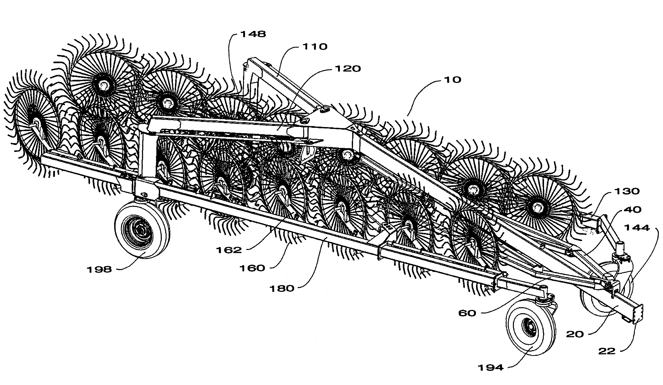
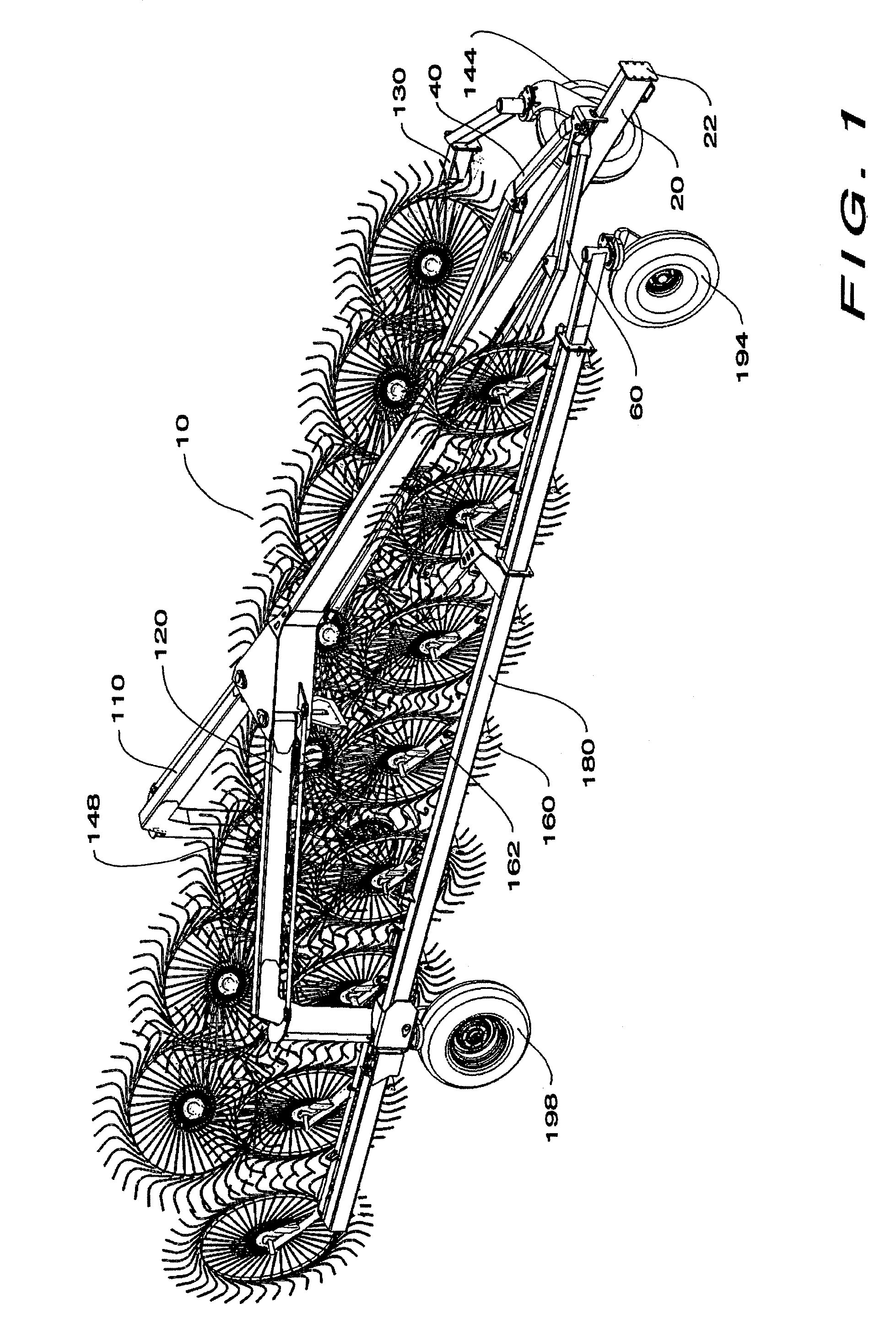
[0026]With reference to FIG. 1, one non-limiting embodiment of the inventive rake apparatus is generally designated by the reference number 10. The rake apparatus 10 includes a tongue assembly 20, which includes a hitch 22 at a forward end (note that the hitch need not be connected at the very end of the tongue assembly, but can be positioned somewhat toward the middle). The rake apparatus is configured to be pulled forward by connection with the hitch 22. As viewed facing forward, toward the direction of travel, a left rake arm assembly 130 and a right rake arm assembly 180 each include a plurality of tined rake wheels 160 attached to the rake arm assemblies 130 and 180 by a plurality of rake wheel arms 162. The left rake arm assembly 130 also includes rake arm wheels 144 and 148, and the right rake arm assembly 180 includes rake arm wheels 194 and 198. The rake arm assemblies 130 and 180 are attached to the tongue 20 at the front by a left front rake arm positioner 40 and a right ...


PUM


Abstract

A rake apparatus includes a tongue with a hitch, front rake arm positioners each pivotally connected to a forward portion of the tongue assembly, rear rake arm positioners pivotally connected to a rear portion of the tongue assembly, and rake arm assemblies including a rake arm assembly front end and a rake arm assembly back end. The rake arm assemblies are pivotally connected to one of the front rake arm positioners and one of the rear rake arm positioners. Distances between the rake arm assembly front ends and the tongue are greater when the rake arm assemblies are in an operating position than when they are in a traveling position. The rake arm assembly back end of each of the rake arm assemblies is positioned farther in the forward direction when the rake arm assemblies are in the operating position than when the rake arm assemblies are in the traveling position.

Description

BACKGROUND OF THE INVENTION[0001]1. Field of the Invention[0002]This invention relates to an agricultural rake device, specifically a Bifold or V-rake type. In one non-limiting embodiment, the Bifold rake is used for raking hay.[0003]2. Description of the Related Art[0004]Agricultural rakes are used to form windrows from cut crops, such as, for example, hay, straw and grasses. It is a typical agricultural process to cut these crops, rake or merge them into windrows where additional drying may occur, collect and store the crops, and subsequently feed the crops to livestock.[0005]Modern power equipment for raking cut forage employs rotating tined wheels and particularly banks of rotating tined wheels that are moved through a field of cut forage to form windrows. These banks of wheel rakes can be quite wide to reduce both the time and number of passes required to rake a field. Because of the wide widths employed by rakes, they typically will have pivot points on each rake arm in order ...

Claims


Application Information

Patent Timeline
Patent Type & Authority Patents(United States)
IPC IPC(8): A01D76/00
CPCA01D78/146A01B73/067
Inventor MARGGI, JEFFBASSETT, WILLIAM
Owner KUHN NORTH AMERICA
Why Eureka
Try Eureka