Collapsible frame for portable shelter

a portable shelter and frame technology, applied in the field of portable shelters, can solve the problems of complex structure, inconvenient use, and easy breakage of parts, and achieve the effects of reducing labor intensity, reducing costs, and increasing stability and durability

Inactive Publication Date: 2009-09-08
TBA CORP
View PDF11 Cites 33 Cited by
  • Summary
  • Abstract
  • Description
  • Claims
  • Application Information

AI Technical Summary

Benefits of technology

[0006]This invention is for a shelter frame which, when combined with a fabric canopy, can be used outdoors or in large indoor areas and is designed to provide added stability and durability. By unfolding and spreading the frame components, this shelter frame can be deployed quickly with minimal personnel. One of the features of this invented shelter frame is its rapid deployment. Because the frame can be erected quickly and folded and taken down in a few minutes, it is properly suited to use under emergency conditions for command shelters, military shelters, decontamination shelters and temporary housing.
[0008]In one embodiment, the wall support system is a dual X-connection system made of a plurality of crossing elongate connection members, wherein one end of each side of the X-connection system has a slide block with a runner that is slideably mounted in a guide in a support leg and the other end of each side of the X-connection system is fixed to the support leg such that one end of the X-connection system moves freely upward or downward relative the other end to permit expanding and narrowing of the X-connection system to adjust the relative position of adjacent ribs.

Problems solved by technology

However, most of the traditional shelter frames are so weak that the parts are easily broken and the shelter itself is eventually rendered useless after transport or use.
Additionally, the shelters typically are complicated and inconvenient to use and require much time and man power to set up and take down.

Method used


Image

  • Collapsible frame for portable shelter
  • Collapsible frame for portable shelter
  • Collapsible frame for portable shelter

Examples


Embodiment Construction

[0021]The invention will now be described in the following detailed description with reference to the drawings, wherein preferred embodiments are described in detail to enable practice of the invention. Although the invention is described with reference to these specific preferred embodiments, it will be understood that the invention is not limited to these preferred embodiments. But to the contrary, the invention includes numerous alternatives, modifications and equivalents as will become apparent from consideration of the following detailed description.

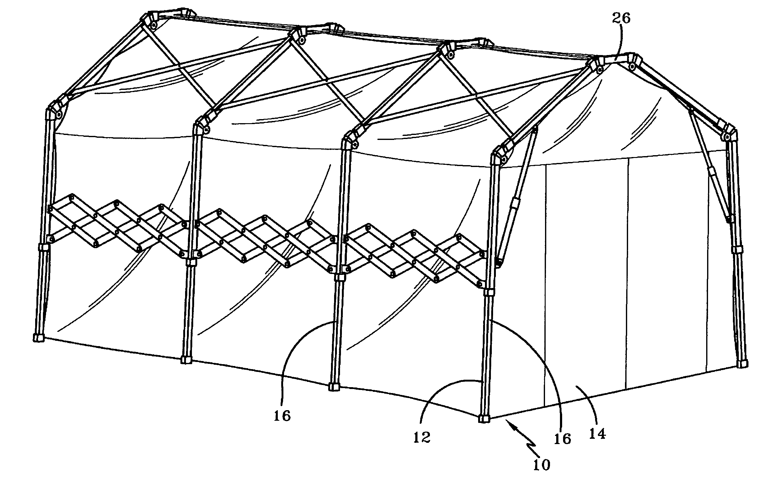
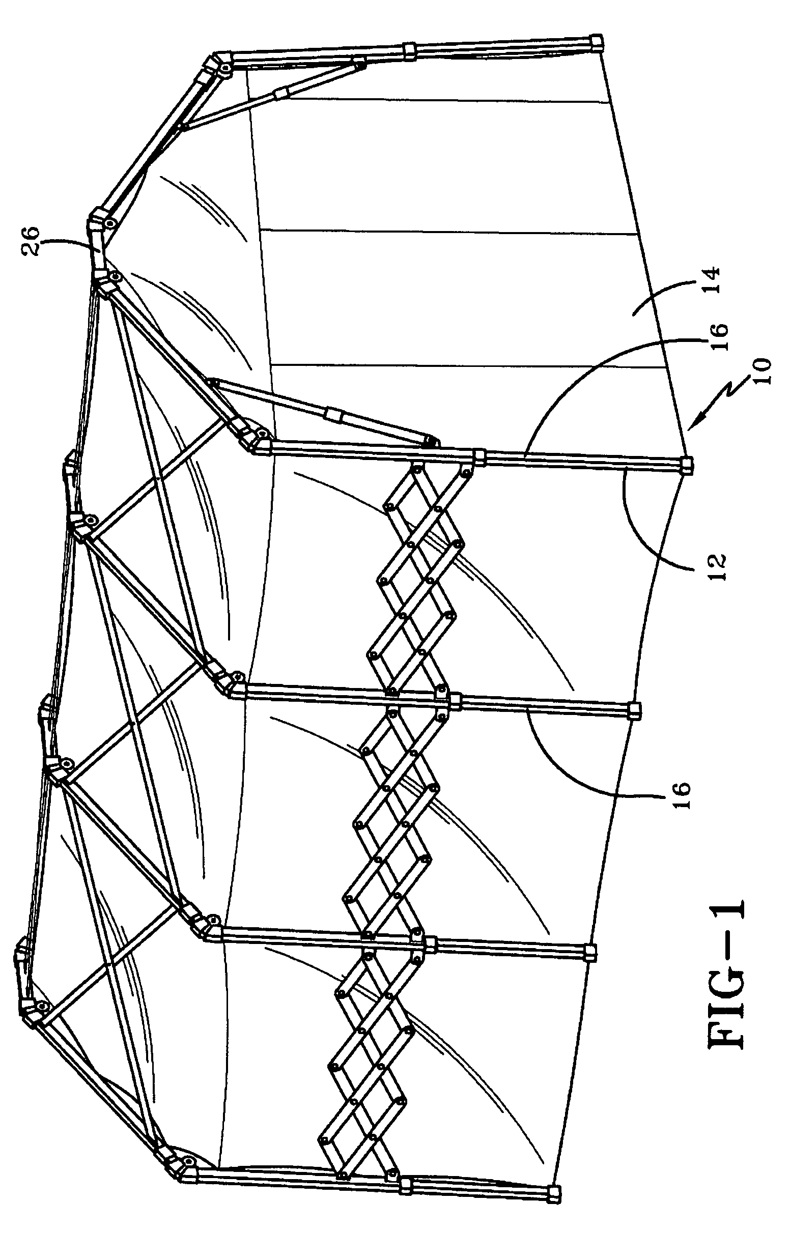
[0022]Referring now to the drawings, FIG. 1 shows a lightweight yet sturdy free-standing portable shelter, indicated generally by numeral 10, according to one embodiment of the invention. The shelter 10 comprises a rigid frame 12 that supports a shelter canopy 14. The frame 12 is desirably made from aluminum and / or plastic injection molding. The canopy 14 is desirably made of nylon, polyester, or other suitable material. In one desi...


PUM


Abstract

A portable shelter having a frame that is separately collapsible in a transverse direction and a longitudinal direction of the shelter to facilitate transportation and storage of the shelter. The frame includes a plurality of ribs, each rib comprising two support legs and at least three roof members forming a generally inverted U-shape when in an erect configuration. The support legs and the roof members are connected with foldable joints such that each rib may be collapsed in the transverse direction to a collapsed configuration wherein width of the rib is narrower in the collapsed configuration than when in the erect configuration. The frame also includes a wall support system connecting adjacent ribs. The wall support system is collapsible in the longitudinal direction to adjust the relative position between adjacent ribs.

Description

BACKGROUND OF THE INVENTION[0001]1. Field of Invention[0002]This invention relates to the field of portable shelters, and more particularly, to a shelter frame that can be rapidly deployed and erected while providing superior strength and durability.[0003]2. Description of Related Art[0004]It is known to erect portable shelters during times of emergency for use as command shelters, decontamination stations, mobile hospitals and temporary housing. These shelters, commonly referred to as emergency portable shelters, desirably are easy and quick to deploy and take down. They also should be lightweight to permit easy transportation, yet be extremely durable because of their use in inclement weather including high wind and heavy rainfall. Ideally, these portable shelters are free-standing. One example of a shelter is illustrated in commonly assigned Korean Patent Application No. 10-2005-0113339.[0005]Many governmental and rescue agencies and organizations provide such portable shelters i...

Claims


Application Information

Patent Timeline
Patent Type & Authority Patents(United States)
IPC IPC(8): E04H15/38E04H15/50
CPCE04H15/52E04H15/505E04H15/46
Inventor YOON, KERN SIK
Owner TBA CORP
Why Eureka
Try Eureka