Wire basket pathway system

a technology of wire basket and pathway system, which is applied in the direction of suspension arrangement of electric cables, floors, buildings, etc., can solve the problems of limiting the access of cable pathways, limiting the spacing of cable pathways, and limiting the number of cable pathways in existing cable support systems, so as to facilitate the rerouting of cables and increase strength and rigidity. , the effect of increasing the rigidity

Inactive Publication Date: 2009-09-08
PANDUIT
View PDF26 Cites 24 Cited by
  • Summary
  • Abstract
  • Description
  • Claims
  • Application Information

AI Technical Summary

Benefits of technology

[0010]The present invention further relates to an improved arrangement for a cable pathway system which facilitates rerouting of the cables and the incorporation of additional cables.
[0011]The present invention relates still further to improved cable tray wire frames having substantially increased strength and rigidity.

Problems solved by technology

One problem encountered in these prior art cable support systems is the presence of sharp edges in the cable tray assemblies which are capable of cutting the cable's outer protective sheathing.
In addition, increasing the number of cables within the confined space of the raised floor system restricts access to cable pathways which is required for carrying out maintenance and repair functions.
The ability to vary the horizontal and vertical positioning of cable pathways in a controlled manner for improving cooling air circulation, optimizing cable pathway spacing and providing additional cable pathways is also limited in existing cable support systems.

Method used


Image

  • Wire basket pathway system
  • Wire basket pathway system
  • Wire basket pathway system

Examples


Embodiment Construction

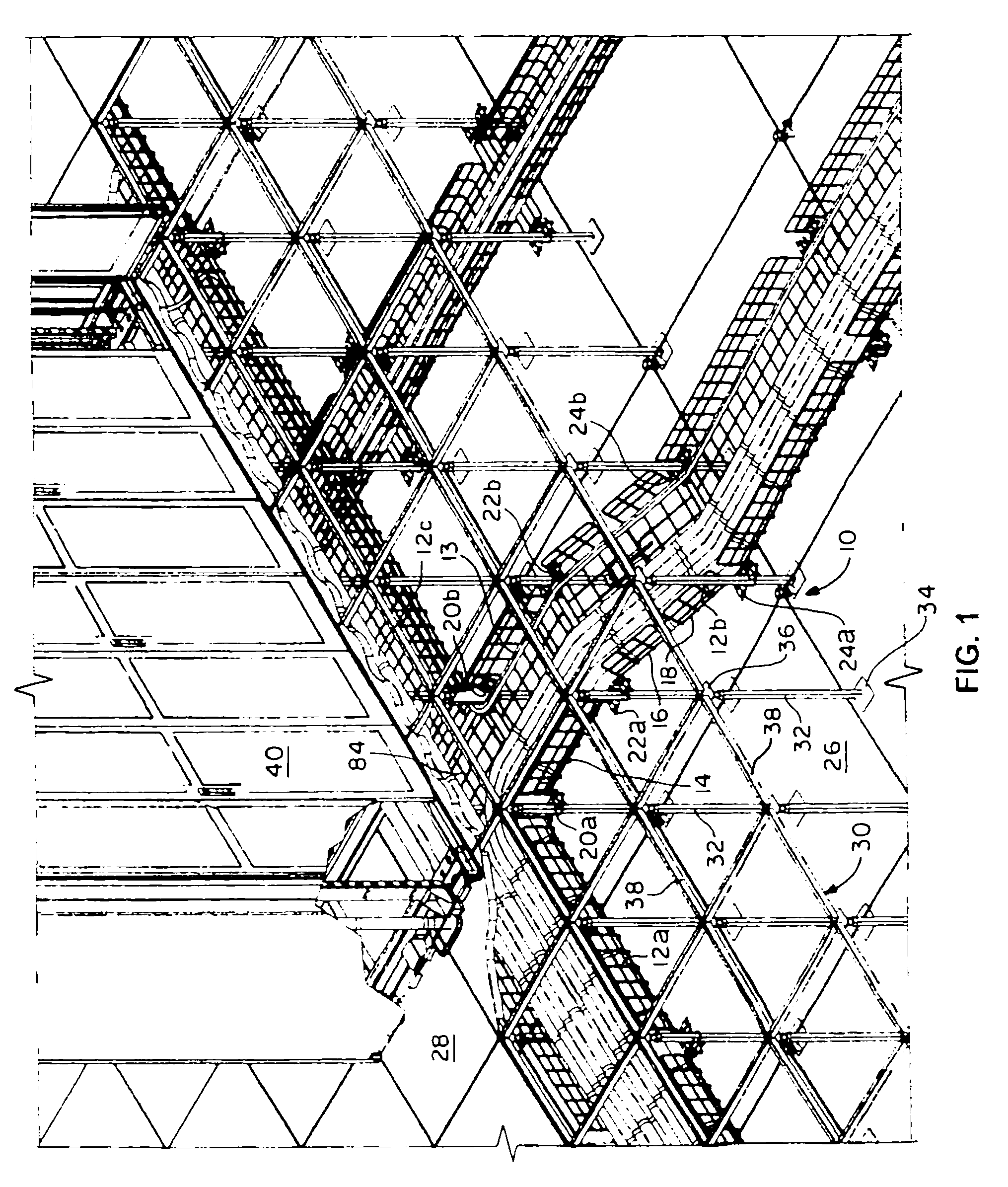
[0048]Referring to FIG. 1, there is shown a perspective view of an improved wire basket pathway system 10 in accordance with the principles of the present invention. The wire basket pathway system 10 provides for plural cable runs 12a, 12b and 12c, which are shown as an example, as the present invention is adapted for use with virtually any number of cable runs. Each of these three cable runs 12a, 12b and 12c includes plural cables carrying electronic signals. The wire basket pathway system 10 may also include one or more optical cables 13, as well as, possibly power cables which are not shown in the figure for simplicity.

[0049]The first, second and third cable runs 12a, 12b and 12c are disposed between a first lower floor 26 and a second raised floor 28. Electronic instrumentation is disposed on the second raised floor 28 and is typically enclosed in one or more cabinets 40.

[0050]The cable runs 12a, 12b and 12c are positioned on and supported by the inventive wire basket pathway sy...


PUM


Abstract

A pedestal bracket assembly includes a support clamp and a support plate attached to the support clamp. The support clamp is capable of engagement with a vertical support member in a fixed manner. The support plate has an opening formed therein and is adapted for engagement with at least one wire basket. The opening is configured to receive the vertical support member. The support plate is also moveably connected to the support clamp such that the support plate is rotatable about the vertical support member. The pedestal bracket assembly also includes a plurality of retainer clips spaced apart from each other and releasably attached to the support plate.

Description

CROSS-REFERENCE TO RELATED APPLICATIONS[0001]This application is a divisional of U.S. patent application Ser. No. 11 / 930,376, filed Oct. 31, 2007, which claims priority to U.S. provisional patent application Ser. No. 60 / 948,071 filed Jul. 5, 2007.FIELD OF INVENTION[0002]This invention relates generally to the positioning, support and protection of cables, and is particularly directed to wire basket arrangements for maintaining pathways of cables securely and safely in position in a raised floor system.BACKGROUND OF THE INVENTION[0003]The widespread use of electronic systems in business and industry has led to the requirement to route large numbers of cables throughout the work environment. Various types of cable tray assemblies are used as a support system for carrying these cables throughout various locations in buildings and other commercial structures.[0004]Attempts to provide additional space to accommodate greater numbers of cables have led to the development of raised floor sy...

Claims


Application Information

Patent Timeline
Patent Type & Authority Patents(United States)
IPC IPC(8): H02G7/00A44B99/00
CPCE04F15/0247H02G3/0443H02G3/0608H02G3/385Y10T24/44026Y10T403/606Y10T24/44
Inventor DAVIS, DAVID R.WASZAK, DENNIS J.BRZEZNIAK, STANLEY A.
Owner PANDUIT
Why Eureka
Try Eureka