Impact mechanism

a technology of impact mechanism and rotating force, which is applied in the direction of portable percussive tools, boring/drilling equipment, drilling machines and methods, etc., can solve the problems of high impact rotational force and the ability to readily adjust the impact for

Inactive Publication Date: 2009-09-15
GRAND
View PDF13 Cites 26 Cited by
  • Summary
  • Abstract
  • Description
  • Claims
  • Application Information

AI Technical Summary

Benefits of technology

[0006]In accordance with one aspect of the present invention there is disclosed a novel impact mechanism for use with a drive motor. The impact mechanism comprises a drive engaging member for engaging a rotatable output of a drive motor for rotation therewith about a longitudinal axis. A tool bit retaining member is operatively inter-connected with the drive engaging member for rotation with respect to the drive engaging member about the longitudinal axis. The tool bit retaining member has a main body portion, an anvil portion securely attached thereto for co-rotation with the main body portion, and a tool bit retaining means securely attached thereto for co-rotation with the main body portion. A hammer member is mounted on one of the drive engaging member and the tool bit retaining member for movement between an anvil contact position whereat force is transmitted from the hammer member to the anvil portion so as to create a moment about the longitudinal axis, and a release position whereat the hammer member is temporarily removed from the anvil portion. There is a guide means for moving the hammer member between the anvil contact position and the release position when the drive engaging member is rotated with respect to the tool bit retaining member. A spring means is operatively interconnected between the drive engaging member and the hammer member for biasing the hammer member to the anvil contact position. In use, rotation of the drive engaging member about the longitudinal axis causes the hammer member to move from its anvil contact position towards its release position, thereby storing potential energy in the spring means. When the hammer member reaches the release position, the hammer member is forcefully propelled by the spring means and the rotation of the drive engaging member to impact on the anvil portion, thus urging the tool bit retaining member to forcefully rotate about the longitudinal axis.

Problems solved by technology

However, it is not known in the prior art to provide a portable assembly that is operatively engageable with the chuck of an electric drill or the like, which assembly provides a high impact rotational force, for turning a threaded fastener into a receiving article, such as a piece of wood, or removing a threaded fastener from a co-operating threaded shaft, and so on.
It is also not known in the prior art to be able to readily adjust the impact rotational force of the impact driver.

Method used


Image

  • Impact mechanism
  • Impact mechanism
  • Impact mechanism

Examples


Embodiment Construction

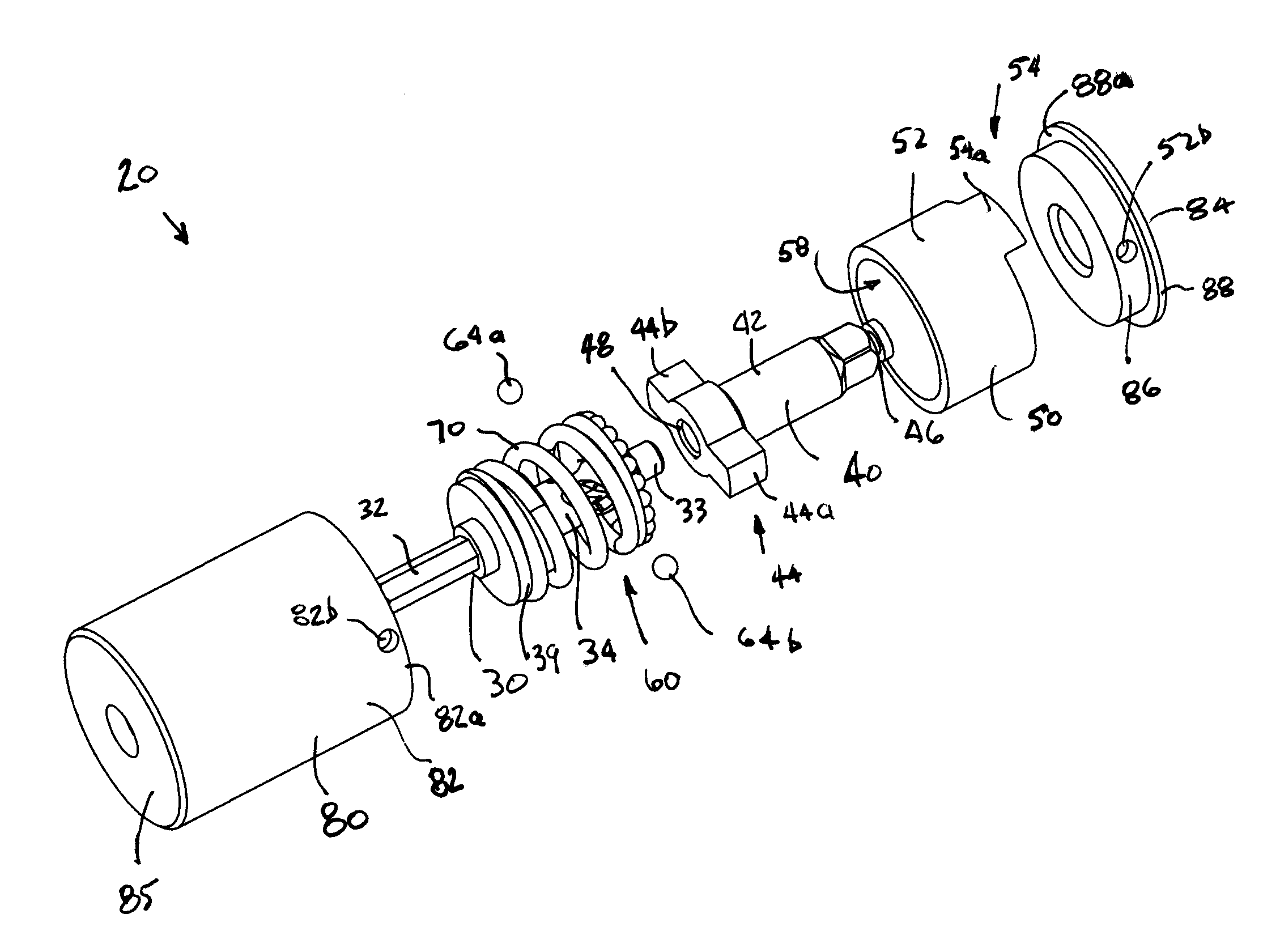
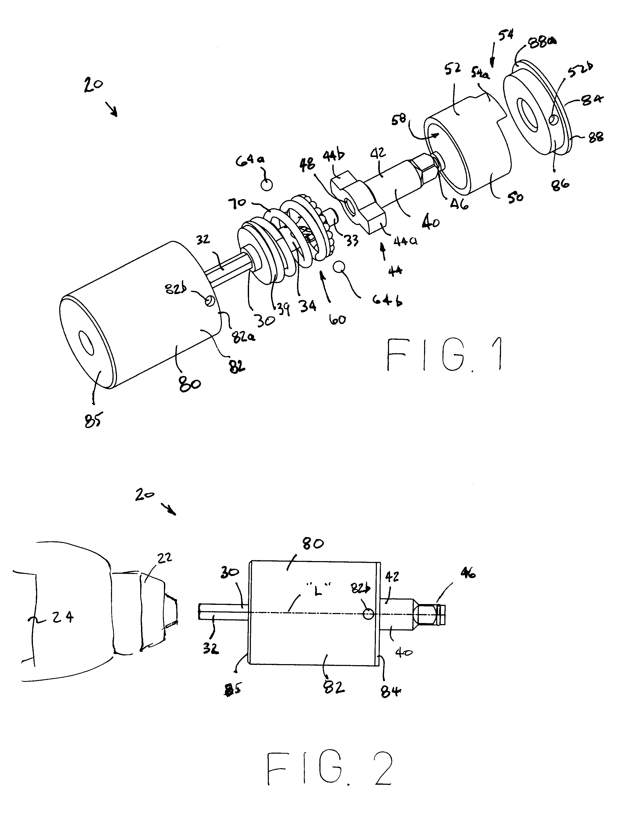
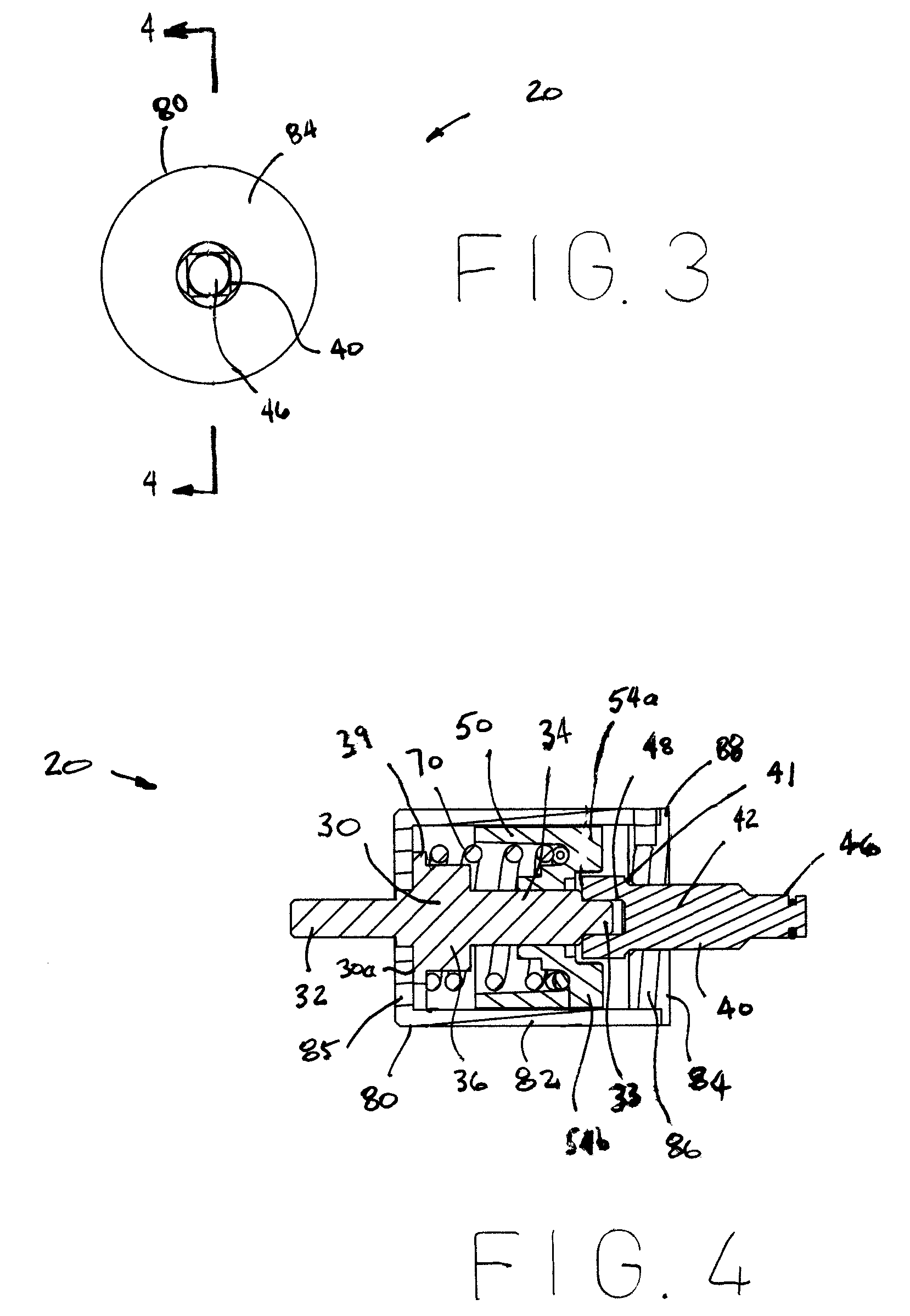
[0028]Referring to FIGS. 1 through 19 of the drawings, it will be noted that FIGS. 1 through 16 illustrate a first preferred embodiment of the impact mechanism of the present invention, and FIGS. 17 through 19 illustrate a second preferred embodiment of the impact mechanism of the present invention.

[0029]Reference will now be made to FIGS. 1 through 16, which show a first preferred embodiment of the impact mechanism of the present invention, as indicated by general reference numeral 20. The impact mechanism 20 is for use with a drive motor 22. The impact mechanism 20 comprises a drive engaging member 30 for engaging a rotatable output, such as a chuck 24, of a drive motor 22, such as an electric drill, for rotation therewith about a longitudinal axis “L” about which the drive engaging member 30 rotates.

[0030]In the first preferred embodiment as illustrated, the drive engaging member 30 comprises a chuck-engageable portion 32 for engagement into the chuck of a drill (not shown). The ...


PUM

PropertyMeasurementUnit
forceaaaaaaaaaa
potential energyaaaaaaaaaa
diameteraaaaaaaaaa

Abstract

An impact mechanism comprises a drive motor engaging member and a tool bit retaining member rotatably inter-connected therewith. The tool bit retaining member has a main body portion, an anvil portion securely attached thereto for co-rotation therewith, and a tool bit retaining portion securely attached thereto for co-rotation with the main body portion. A hammer member is mounted on the drive engaging member for movement between an anvil contact position wherein force is transmitted from the hammer member to the anvil portion, and a release position whereat the hammer member is temporarily removed from the anvil portion. A spring biases the hammer member to the anvil contact position. In use, the hammer member to move from its anvil contact position towards its release position, wherein the hammer member is propelled by the spring and the rotation of the drive engaging member to impact on the anvil portion.

Description

[0001]This application is a non-provisional application claiming priority to U.S. provisional patent application Ser. No. 60 / 970,259 filed on Sep. 5, 2007 now abandoned, which is herein incorporated by reference.FIELD OF THE INVENTION[0002]The present invention relates to impact mechanisms, and more particularly to impact mechanisms that are selectively mountable on an electric drill or the like.BACKGROUND OF THE INVENTION[0003]It is known to use a series of impacts of a hammer member on an anvil member to provide a significant force and highly effective rotational force in an impact driver. However, it is not known in the prior art to provide a portable assembly that is operatively engageable with the chuck of an electric drill or the like, which assembly provides a high impact rotational force, for turning a threaded fastener into a receiving article, such as a piece of wood, or removing a threaded fastener from a co-operating threaded shaft, and so on. It is also not known in the...

Claims


Application Information

Patent Timeline
Patent Type & Authority Patents(United States)
IPC IPC(8): B25D11/00
CPCB25B21/026B25B21/02
Inventor GRAND, GERARD M.BEAUCHAMP, FERN
Owner GRAND
Why Eureka
Try Eureka