Device for determining a hemodynamic parameter

a hemodynamic parameter and device technology, applied in the field of devices for determining the hemodynamic parameter of patients, can solve the problems of reducing the availability of increasing the stress of the patient being monitored, and reducing the availability of that personnel for other tasks, so as to improve the accuracy of stroke volume determination and improve the determination of the transition between systole and diastole.

Active Publication Date: 2009-09-15
PULSION MEDICAL SYSTEMS SE
View PDF11 Cites 11 Cited by
  • Summary
  • Abstract
  • Description
  • Claims
  • Application Information

AI Technical Summary

Problems solved by technology

However, this is connected with some effort and expenditure, particularly with the administration of a bolus injection, and this means additional stress for the patient being monitored, as well as putting a time burden on the personnel involved, thereby reducing the availability of that personnel for other tasks.

Method used


Image

  • Device for determining a hemodynamic parameter
  • Device for determining a hemodynamic parameter
  • Device for determining a hemodynamic parameter

Examples


Embodiment Construction

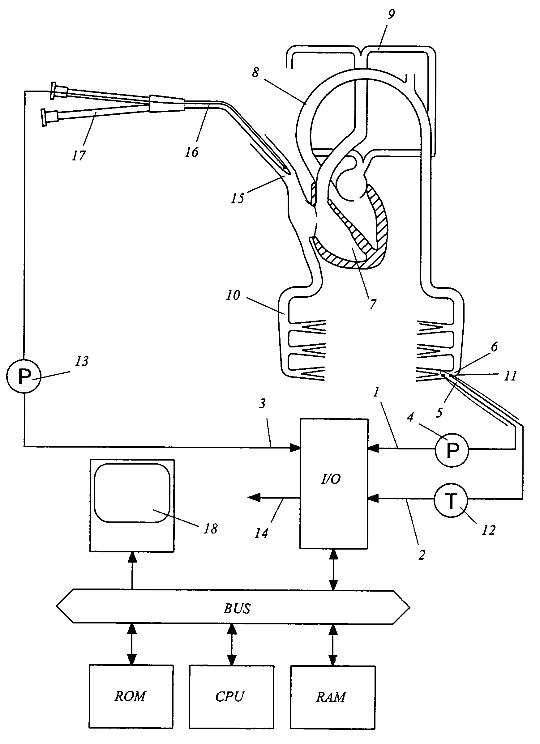
[0044]The device from FIG. 1 has an input / output sub-system (I / O) with three input channels 1, 2, 3.

[0045]A pressure signal that corresponds at least approximately to the aorta pressure of the patient is continuously read in by way of the first input channel 1. This can be an analog sensor signal, which is digitalized by means of an analog / digital converter, or a digital signal is already read in from an external pressure measurement transformer 4.

[0046]In practice, an arterial pressure that is measured, preferably as close to the aorta as possible, by way of an arterial catheter 5, serves as a pressure that approximately corresponds to the aorta pressure. A leg artery 6 can serve as the measurement site, as is indicated in the outlined segment of the vascular system with heart 7, aorta arch 8, pulmonary circulatory system 9, and body circulatory system 10.

[0047]The arterial catheter 5 furthermore contains a temperature sensor 11, which can be used for a thermo-dilution measurement ...


PUM


Abstract

An arterially measured pressure signal is continuously read in and temporarily stored in the working memory (RAM). The function p(t) is processed by the central processing unit (CPU), to calculate the heart / time volume PCCO and other hemodynamic parameters. The calculation comprises the following steps: The systemic vascular resistance SVRk is calculated for the current pulse period. The stroke volume SVk is numerically determined from the pressure values of a pulse period, according to the following equation:SVk∝∑(pi⁡(t)SVRk+Ck⁡(pi)⁢ⅆpiⅆt)with the compliance C(p)=(MAP−CVP)k / [SVR·<dp / dt>k]·ƒ(p). The difference between the mean arterial pressure MAP and the central venous pressure CVP, and the mean incline of the pressure curve in the diastole <dp / dt>, are re-determined for the current pulse period. The heart / time volume calculated in the current pulse period results from PCCOk=SVk·HR. Therefore, continuous recalibration of the systemic vascular resistance and of the compliance takes place, from the continuously determined pressure measurement data.

Description

BACKGROUND OF THE INVENTION[0001]1. Field of the Invention[0002]The present invention relates to a device for determining a hemodynamic parameter of a patient by means of pulse contour analysis.[0003]2. The Prior Art[0004]The determination of hemodynamic parameters, particularly the heart / time volume (cardiac output CO), by means of pulse contour analysis on the basis of a non-linear air dome model, has been described in detail in German Patent No. DE 198 14 371 A1 as well as in the literature listed there, which goes even further. The fundamental measurement variable for pulse contour analysis is a pressure that approximately corresponds to the aorta pressure, which is continuously measured, for example, by means of an arterial catheter in a leg artery. A pulse contour analysis system from Pulsion Medical Systems AG is commercially available under the designation PiCCO.[0005]Significant variables in the determination of hemodynamic parameters, proceeding from the function P(t), i.e...

Claims


Application Information

Patent Timeline
Patent Type & Authority Patents(United States)
IPC IPC(8): A61B5/02A61B5/00A61B5/0215A61B5/028A61B5/029A61B5/0295
CPCA61B5/02028A61B5/029A61B5/028A61B5/0215A61B5/02108A61B5/02
Inventor PFEIFFER, ULRICH J.KNOLL, REINHOLDREGH, STEPHAN
Owner PULSION MEDICAL SYSTEMS SE
Why Eureka
Try Eureka