Surface wave communications between a remote antenna and a base station that is co-located with another base station

a remote antenna and co-location technology, applied in the field of communication, can solve the problems of prohibitively expensive implementation of new site b>206/b>, and difficult or impossible to find new site b>206/b>

Active Publication Date: 2009-09-15
T MOBILE INNOVATIONS LLC
View PDF10 Cites 665 Cited by
  • Summary
  • Abstract
  • Description
  • Claims
  • Application Information

AI Technical Summary

Problems solved by technology

Unfortunately, an elevated structure that is properly located to serve cell 208 and that has enough space for a new antenna and base station may be hard to find and may be very expensive.
Thus, new site 206 may be very difficult or impossible to find, and new site 206 may become prohibitively expensive to implement.
Unfortunately, surface wave technology has not been effectively implemented to alleviate the split cell problem described above.

Method used


Image

  • Surface wave communications between a remote antenna and a base station that is co-located with another base station
  • Surface wave communications between a remote antenna and a base station that is co-located with another base station
  • Surface wave communications between a remote antenna and a base station that is co-located with another base station

Examples


example # 1

Example #1

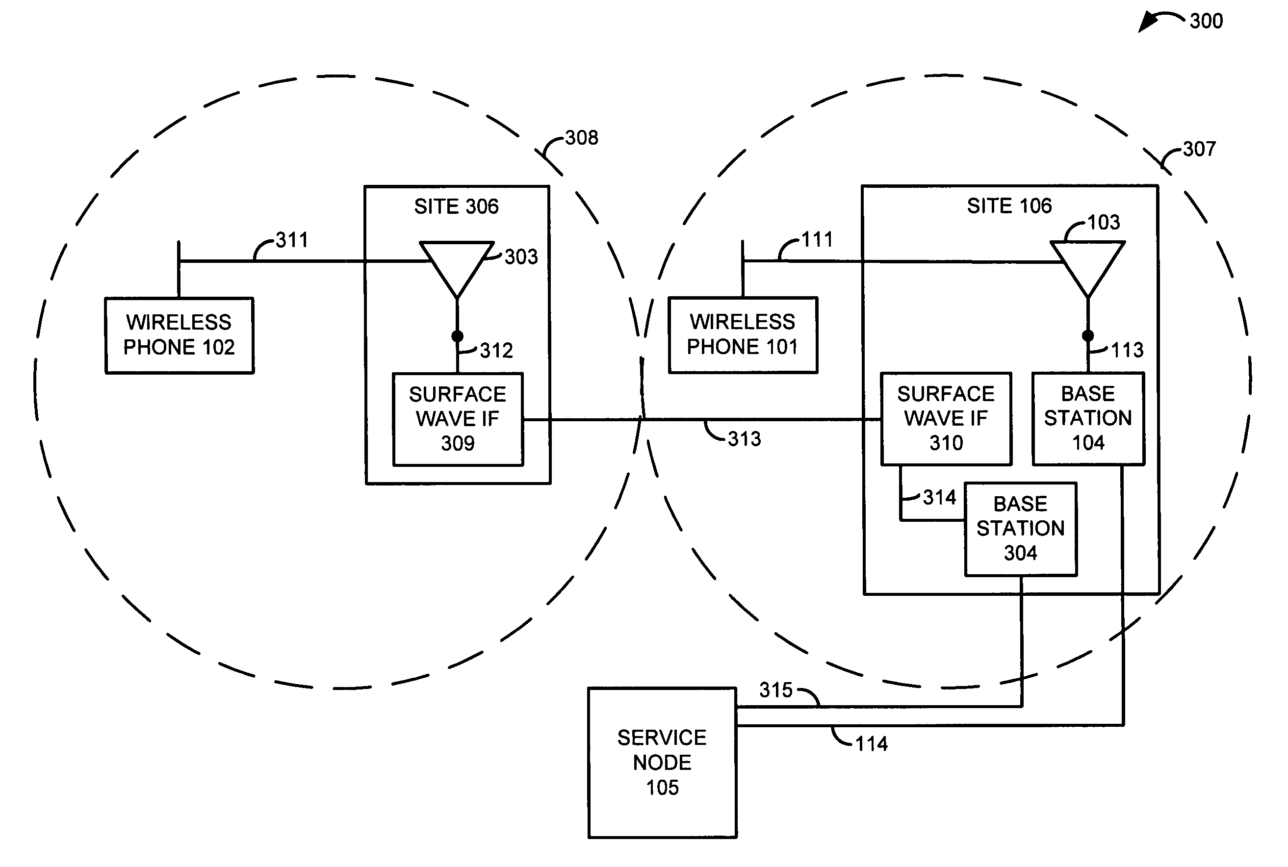
[0039]FIG. 3 illustrates communication system 300 in an example of the invention. Communication system 300 includes antennas 103 and 303, base stations 104 and 304, service node 105, and surface wave interfaces 309-310. Note that former cell 107 (See FIG. 1) has been split into two cells 307 and 308. Existing site 106 retains existing antenna 103 and existing base station 104 to serve new cell 307. New site 306 includes new antenna 303 and new surface wave interface 309 to serve new cell 308.

[0040]Note that new base station 304 and new surface wave interface 310 are located at existing site 106 and not at new site 306. Thus, base stations 104 and 304 are co-located at site 106. In some variations, sites 106 and 306 represent elevated structures, such as buildings or towers. In addition, sites 106 and 306 represent different locations that do not overlap.

[0041]At site 106, antenna 103 exchanges first user communications in a wireless communication format with wireless commu...

example # 4

Example #4

[0046]FIG. 4 illustrates communication system 400 in an example of the invention. Communication system 400 is a variation of communication system 300 that includes service node 105 and sites 106 and 306. Site 306 is configured and operates as described for site 306 in communication system 300. Aside from communications with service node 105, site 106 is configured and operates as described for site 106 in communication system 300. Site 106 is depicted as an elevated structure in communication system 400 (although an elevated structure is not required in all examples). Note that base stations 104 and 304 are co-located the same elevated structure represented by site106.

[0047]Communication system 104 includes cross-connect device 401. Cross-connect device 401 is coupled to communication link 411 that is coupled to base station 104. Cross-connect device 401 is coupled to communication link 412 that is coupled to base station 304. Cross-connect device 401 is coupled to communi...


PUM


Abstract

At a first site, a first antenna exchanges first communications with wireless devices, and exchanges the first communications with a first base station. The first base station exchanges the first communications with a service node. At a second site, a second antenna exchanges second communications with other wireless devices, and exchanges the second communications with a first surface wave interface. The first surface wave interface exchanges the second communications with a second surface wave interface at the first site. The second surface wave interface exchanges the second communications with a second base station at the first site. The second base station exchanges the second communications with the service node. The service node processes the first and second communications to provide a communication service to the wireless devices.

Description

RELATED APPLICATIONS[0001]Not applicableFEDERALLY SPONSORED RESEARCH OR DEVELOPMENT[0002]Not applicableMICROFICHE APPENDIX[0003]Not applicableBACKGROUND OF THE INVENTION[0004]1. Field of the Invention[0005]The invention is related to the field of communications, and in particular, to communications between antennas, base stations, and service nodes.[0006]2. Description of the Prior Art[0007]FIG. 1 illustrates communication system 100 in an example of the prior art. Communication system 100 includes antenna 103, base station 104, and service node 105. Both antenna 103 and base station 104 are located at the same site 106. In most cases, site 106 represents an elevated structure, such as a building or tower.[0008]Antenna 103 exchanges user communications in a wireless communication format with wireless communication devices 101-102 over wireless communication links 111-112. The wireless communication format could be Code Division Multiple Access (CDMA), Global System for Mobile Commun...

Claims


Application Information

Patent Timeline
Patent Type & Authority Patents(United States)
IPC IPC(8): H04M9/00
CPCH01Q1/246H04W28/06H04W88/06
Inventor JOHNSON, HAROLD W.EULER, TIMOTHY D.
Owner T MOBILE INNOVATIONS LLC
Why Eureka
Try Eureka