
Illuminated modular dog leash and collar assembly

a modular, leash technology, applied in the field of leash and collar assemblies, can solve the problems of difficult identification of animals, particularly serious accidents, and difficulty in identifying animals, and achieve the effect of easy identification of animals

Inactive Publication Date: 2009-09-29
TOPLIN KEVIN
View PDF16 Cites 19 Cited by
  • Summary
  • Abstract
  • Description
  • Claims
  • Application Information

AI Technical Summary

Benefits of technology

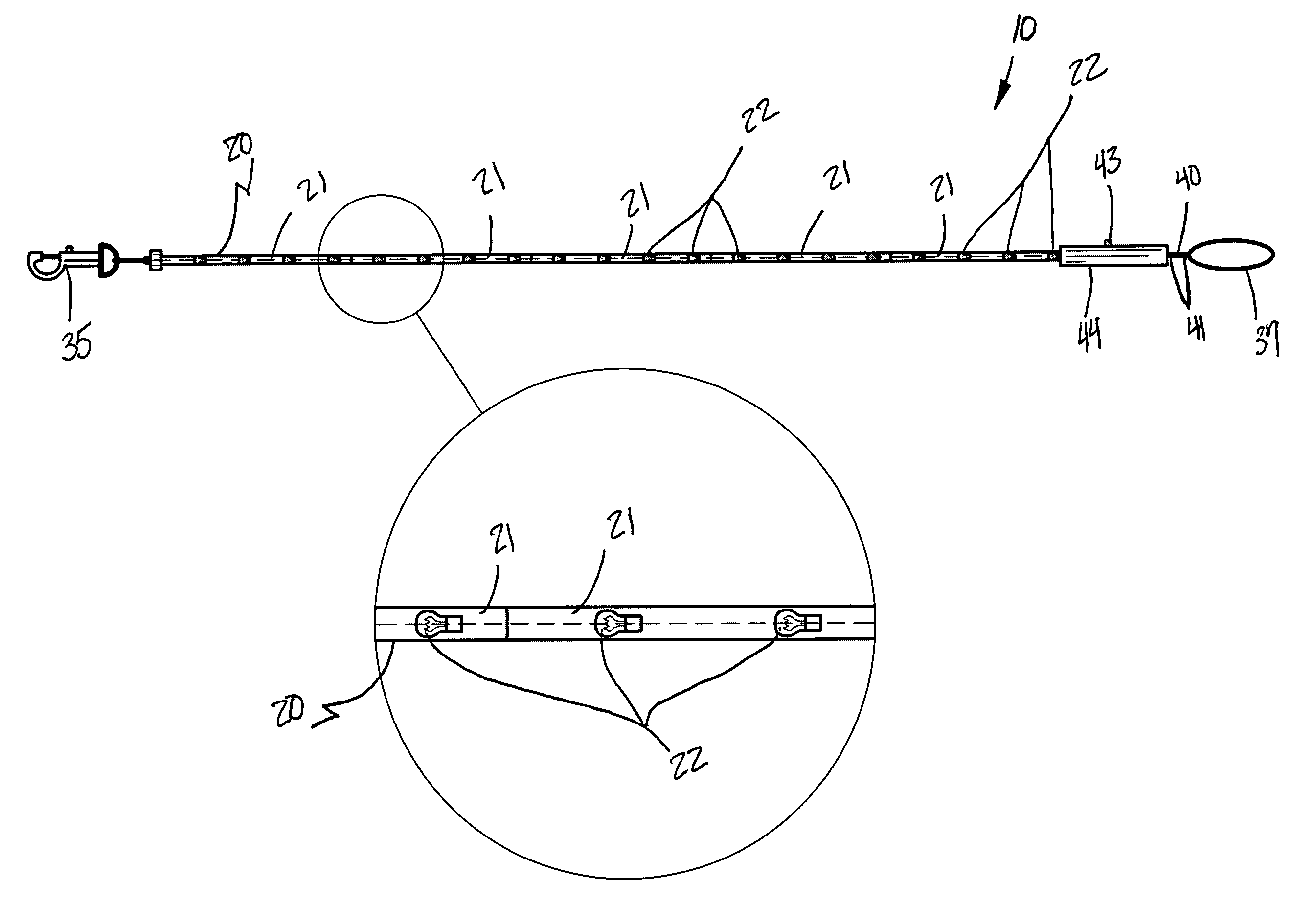
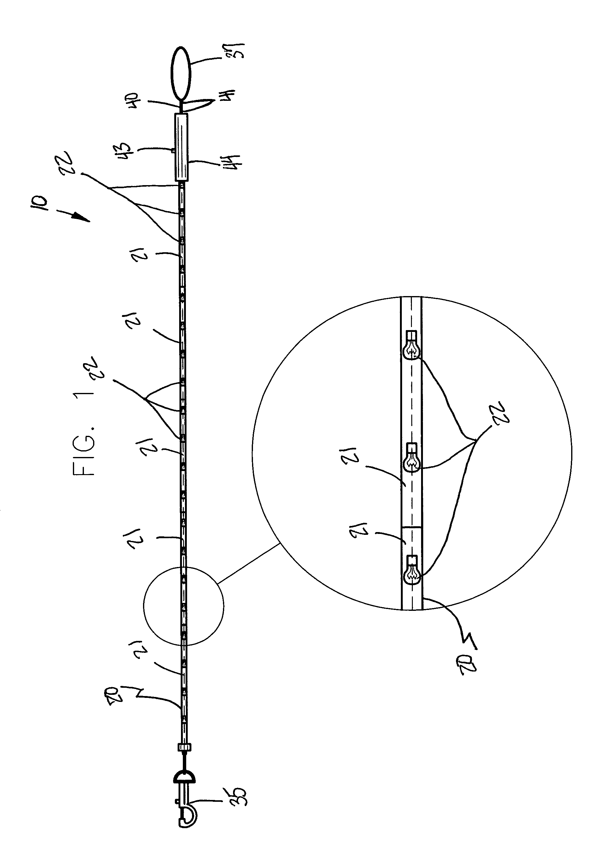
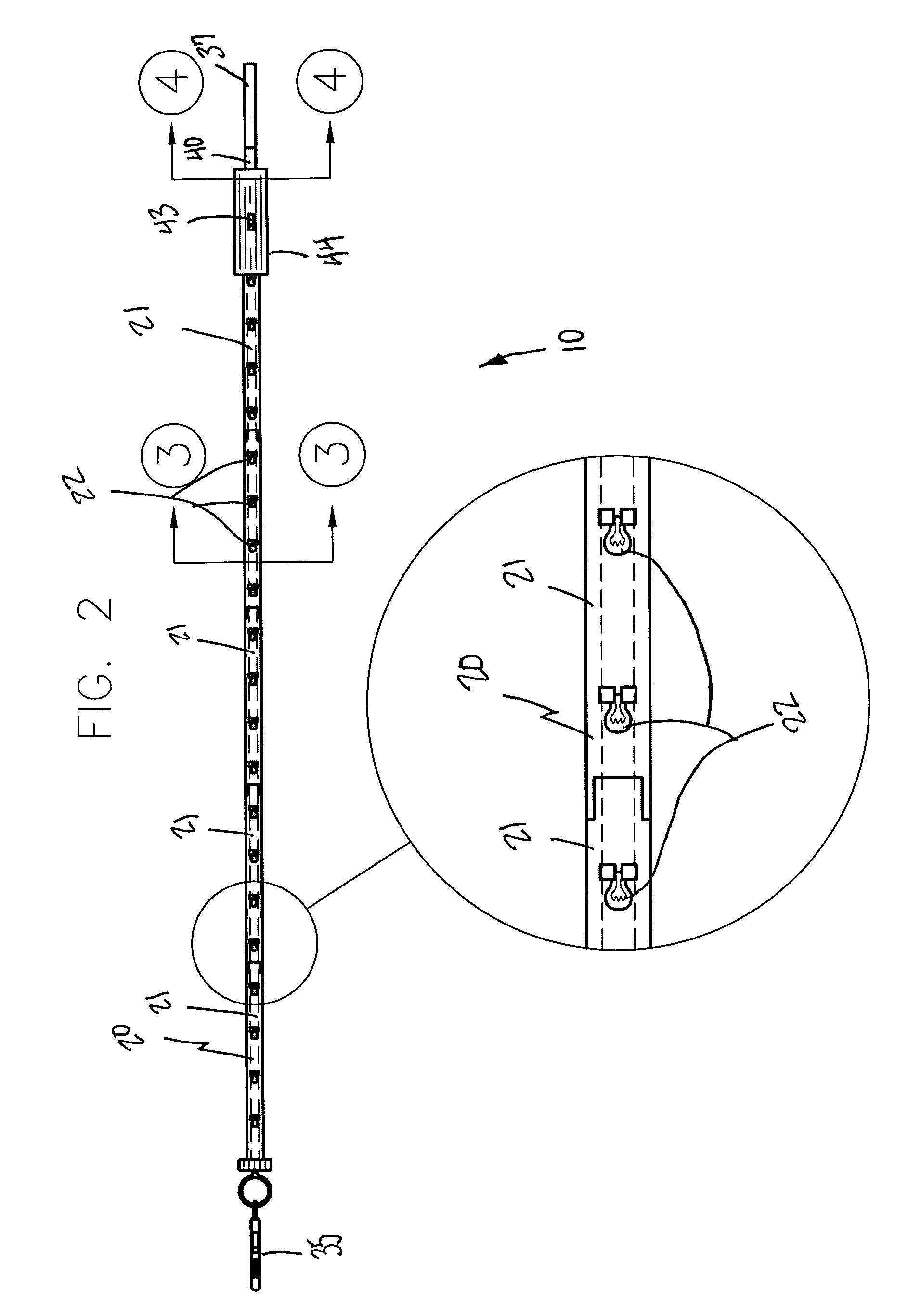
[0011]In view of the foregoing background, it is therefore an object of the present invention to provide an assembly for an illuminated modular dog leash and collar assembly. These and other objects, features, and advantages of the invention are provided by an illuminable animal leash and collar assembly for allowing a caregiver and bystanders to easily identify an animal during low ambient light conditions.
[0012]The assembly includes a leash including a plurality of electrically mated modular segments conveniently connected end-to-end and thereby effectively defining a rectilinear longitudinal shape, wherein such modular segments are interchangeably coupled along a longitudinal length of the leash. Each of the modular segments includes a plurality of illuminable light-emitting sources housed therein and advantageously connected in sequence respectively such that selected ones of the modular segment light-emitting sources effectively illuminate in sync with respect to other ones of the modular segment light-emitting sources.
[0013]Each of the modular segments includes a tubular core conveniently embedded with corresponding ones of the light-emitting sources, and a transparent hollow sleeve removably positioned about the tubular core. Such a sleeve has a unitary and continuous body effectively extending along the entire longitudinal length of the modular segment associated therewith. A collar includes a plurality of electrically mated modular regions. Each of such modular regions includes a plurality of illuminable light-emitting sources housed therein and advantageously connected in sequence respectively such that selected ones of the modular region light-emitting sources effectively illuminate in sync with respect to other ones of the modular region light-emitting sources. Each of the modular segments and the modular regions includes detachably mated conductive male and female couplings advantageously disposed at opposed ends thereof respectively.
[0014]The assembly further includes, in an alternate embodiment, a collar that includes first and second modular regions that have annular shapes provided with electrically mated conductive terminals. A third one of the modular regions has a rectilinear shape conveniently provided with axially opposed conductive terminals removably coupled directly to the first and second modular regions. The leash further includes a fastener connected directly to one end portion thereof. Such a fastener is in electrical communication with an internal power source and is advantageously provided with a conductive terminal removably engaged with the conductive terminals of the first, second and third regions to thereby effectively maintain direct electrical communication with the first, second and third modular regions when the leash is attached to the collar.
[0016]The assembly further includes a mechanism for independently illuminating the selected modular segment and region light-emitting sources respectively such that the modular segment and region light-emitting sources remain effectively non-illuminated based upon the longitudinal length of the handle with respect to a longitudinal length of the leash. Such an independent illuminating mechanism includes a spring-actuated spindle and a flexible cable journaled thereabout. Such a cable has opposed ends directly anchored to the handle and the spindle respectively and conveniently includes a plurality of actuating fingers protruding outwardly therefrom. Each of the fingers is uniquely sized and effectively maintains a unique spatial distance from the associated switch (herein described below) such that associated ones of the fingers advantageously engage associated ones of the switches while traveling along a single travel path and thereby effectively prohibit non-corresponding ones of the fingers and switches from engaging as the cable is extracted and retracted from the compartment (herein described below).

Problems solved by technology

Today's busy and bustling society makes demands upon many persons who choose to keep pets such as dogs and the like such that they do not have the opportunity on a daily basis to walk their animal during daylight hours.
At night, visibility becomes an issue due to significant, if not heavy, automobile and other vehicle traffic in even rural areas.
If a person or animal cannot be seen by a driver of such a vehicle, the risk of accident is particularly serious when crossing the street or otherwise.
Unfortunately, this prior art example poses a safety hazard to drivers if the light is shined into a driver's eyes while operating a motor vehicle.
Unfortunately, the use of fiber optics makes this design susceptible to damage, as well as prohibitively expensive for most pet owners.

Method used


Image

  • Illuminated modular dog leash and collar assembly
  • Illuminated modular dog leash and collar assembly
  • Illuminated modular dog leash and collar assembly

Examples


Embodiment Construction

[0034]The present invention will now be described more fully hereinafter with reference to the accompanying drawings, in which a preferred embodiment of the invention is shown. This invention may, however, be embodied in many different forms and should not be construed as limited to the embodiment set forth herein. Rather, this embodiment is provided so that this application will be thorough and complete, and will fully convey the true scope of the invention to those skilled in the art. Like numbers refer to like elements throughout the figures.

[0035]The assembly of this invention is referred to generally in FIGS. 1-13 by the reference numeral 10 and 10′ is intended to provide an illuminated modular dog leash and collar assembly. It should be understood that the assembly 10 and 10′ may be used to illuminate many different types of animals in many different types of low ambient light conditions and should not be limited in use to only those types of animals and conditions described h...


PUM


Abstract

An illuminated modular dog leash and collar assembly includes electrically mated segments connected end-to-end and defining a rectilinear shape. Each of the segments includes illuminable light-emitting sources housed therein and connected in sequence, a tubular core, and a sleeve removably positioned about the core. The sleeve extends along the entire longitudinal length of the modular segment associated therewith. An extendable handle is removably attached to the leash and spaced from the collar, and is adaptable between alternate longitudinal lengths. A mechanism independently illuminates the light-emitting sources such that the collar and leash selectively illuminate when the pet becomes separated from the caregiver beyond a predetermined distance.

Description

CROSS REFERENCE TO RELATED APPLICATIONS[0001]This application claims the benefit of U.S. Provisional Application No. 60 / 745,468, filed Apr. 24, 2006, the entire disclosure of which is incorporated herein by reference.STATEMENT REGARDING FEDERALLY SPONSORED RESEARCH OR DEVELOPMENT[0002]Not Applicable.REFERENCE TO A MICROFICHE APPENDIX[0003]Not Applicable.BACKGROUND OF THE INVENTION[0004]1. Technical Field[0005]This invention relates to leash and collar assemblies and, more particularly, to an illuminated modular dog leash and collar assembly for allowing a caregiver and bystanders to easily identify an animal during low ambient light conditions.[0006]2. Prior Art[0007]Pet owners, particularly dog owners, take their animals for walks as recreation on generally a daily basis. Very often, such walks are taken beyond or before daylight hours. Today's busy and bustling society makes demands upon many persons who choose to keep pets such as dogs and the like such that they do not have the ...

Claims


Application Information

Patent Timeline
IPC IPC(8): A01K27/00
CPCA01K27/006
Inventor TOPLIN, KEVIN
Owner TOPLIN KEVIN
Learn More