Elevator system

a technology of elevator system and elevator shaft, which is applied in the direction of emergency power supply arrangement, electrical apparatus, instruments, etc., can solve the problems of affecting the safety of people in the building, affecting the safety of the elevator system, and not being able to guarantee the optimal value of the gene algorithm. , to achieve the effect of improving safety and good performan

Active Publication Date: 2009-09-29
KONE CORP
View PDF20 Cites 47 Cited by
  • Summary
  • Abstract
  • Description
  • Claims
  • Application Information

AI Technical Summary

Benefits of technology

[0039]An advantage of the present invention is that by means of the method the evacuation time of a person to be evacuated from especially a high-rise building can made shorter than can be guaranteed with e.g. only use of the stairways. Likewise safety can be improved with the method in a situation in which people move quickly towards the evacuating elevator in an emergency. Another advantage of the present invention is also that when a power limit is in force the elevator system nevertheless achieves surprisingly good performance.
[0040]FIG. 1 presents a flowchart relating to the present invention, which describes the elevator control method in connection with an evacuation situation,
[0041]FIGS. 2a-2c present an example of a way with which people are evacuated in the present invention in a system of three elevators, and
[0042]FIG. 3 presents the equipment needed by the embodiment in an elevator system according to the present invention.

Problems solved by technology

Genetic algorithms do not absolutely guarantee finding the most optimal value, but results achieved in practical applications are very close to it.
This kind of serious exceptional incident can be e.g. a fire, an earthquake, a bomb threat or similar type of event, which is of danger to the people in the building.
This is because a fire can seriously damage an elevator system, in which case elevators are no longer safe to use for evacuating people to the exit floor of the building.
It is possible that the elevator stops working during an elevator run, in which case the elevator car may stop between floors leaving the elevator passengers trapped.
In addition, a fire or smoke may spread strongly, especially along the elevator shaft, in which case the elevator is no longer a safe place owing to the lack of oxygen or the heat.
Also the extinguishing water used for extinguishing fires may damage the electrical parts of the system e.g. by causing short-circuits in the electronics parts of the system.
Additionally in the event of a fire it is not sensible to direct the elevator car to, and then open the doors to, a floor on which the fire has progressed to an advanced stage.
In this case the safety of the people already traveling in the elevator is endangered and the time needed for evacuation becomes longer, if in addition it can be assumed that people have been evacuated from this kind of floor earlier.
In high-rise buildings this is especially prominent, because the safe evacuation of a large number of people along the stairs and out of the building is extremely slow.
The loading of the elevator car and the counterweight are almost always unbalanced and moving the elevator in the so-called light direction (empty car upwards, full car downwards) requires less power than in the so-called heavy direction (empty car downwards, full car upwards).
One problem in the arrangement according to publication U.S. Pat. No. 6,000,505 is that the appliance is not able to forecast its own endurance and a consequence of this can be that the elevator could be performing an evacuation task at exactly the moment some critical component fails owing to e.g. strong heat in a fire incident.
A problem of prior art is that an effective evacuation method in a building in which both the stairways and the elevators can be used for evacuation has not previously been presented.

Method used


Image

  • Elevator system
  • Elevator system
  • Elevator system

Examples


Embodiment Construction

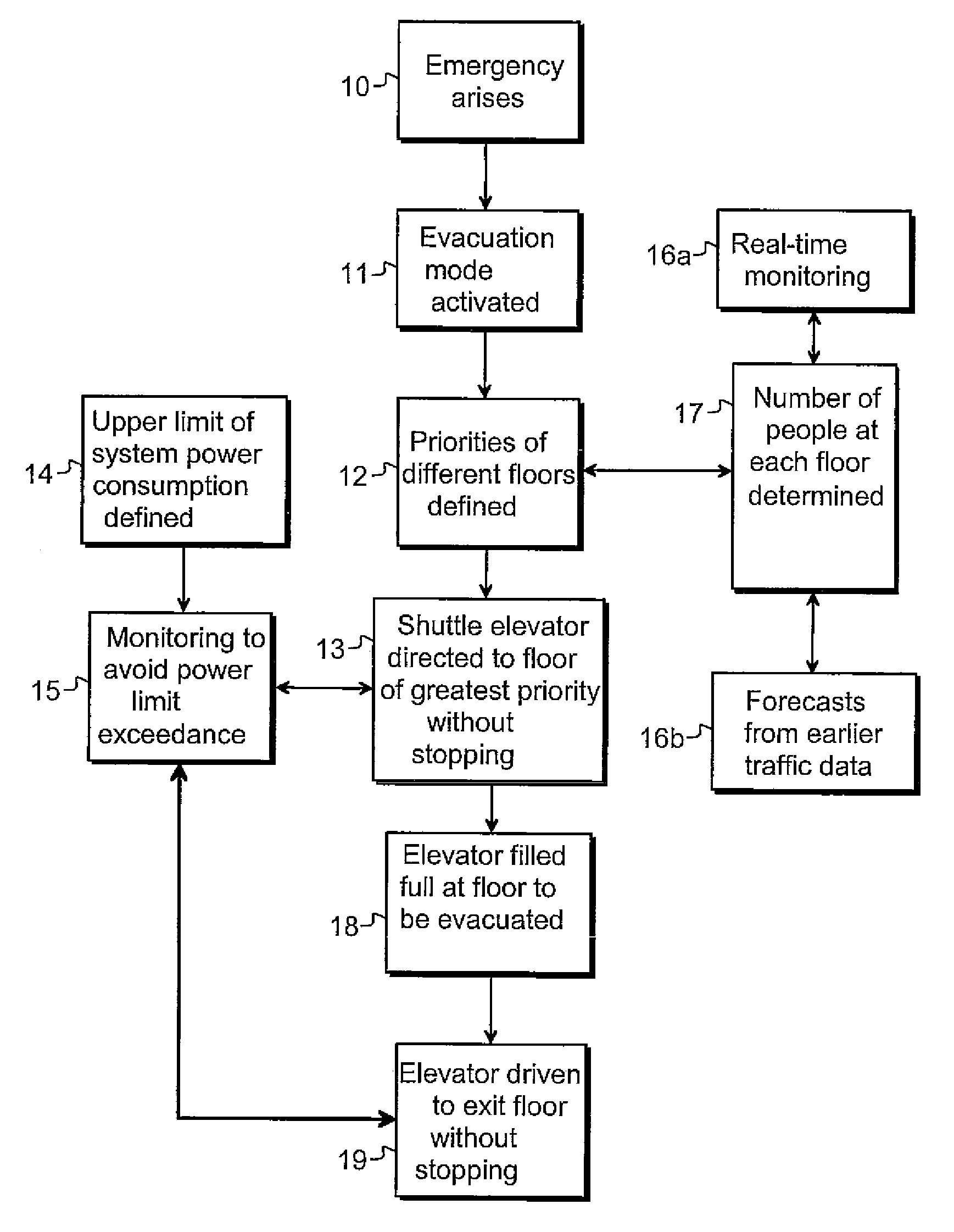
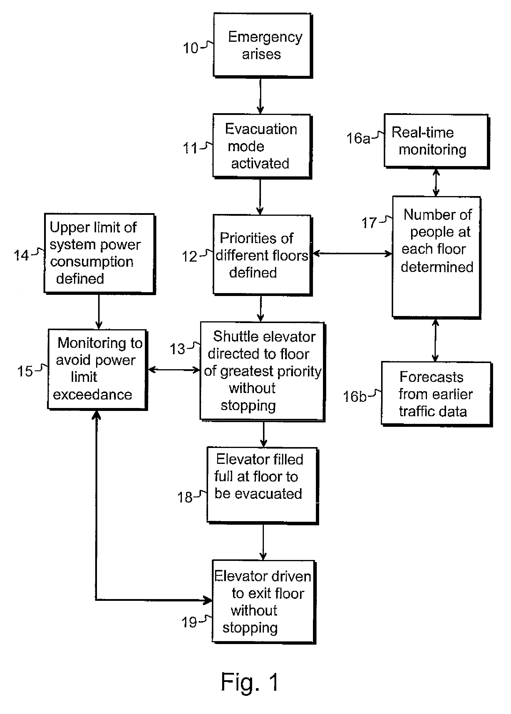
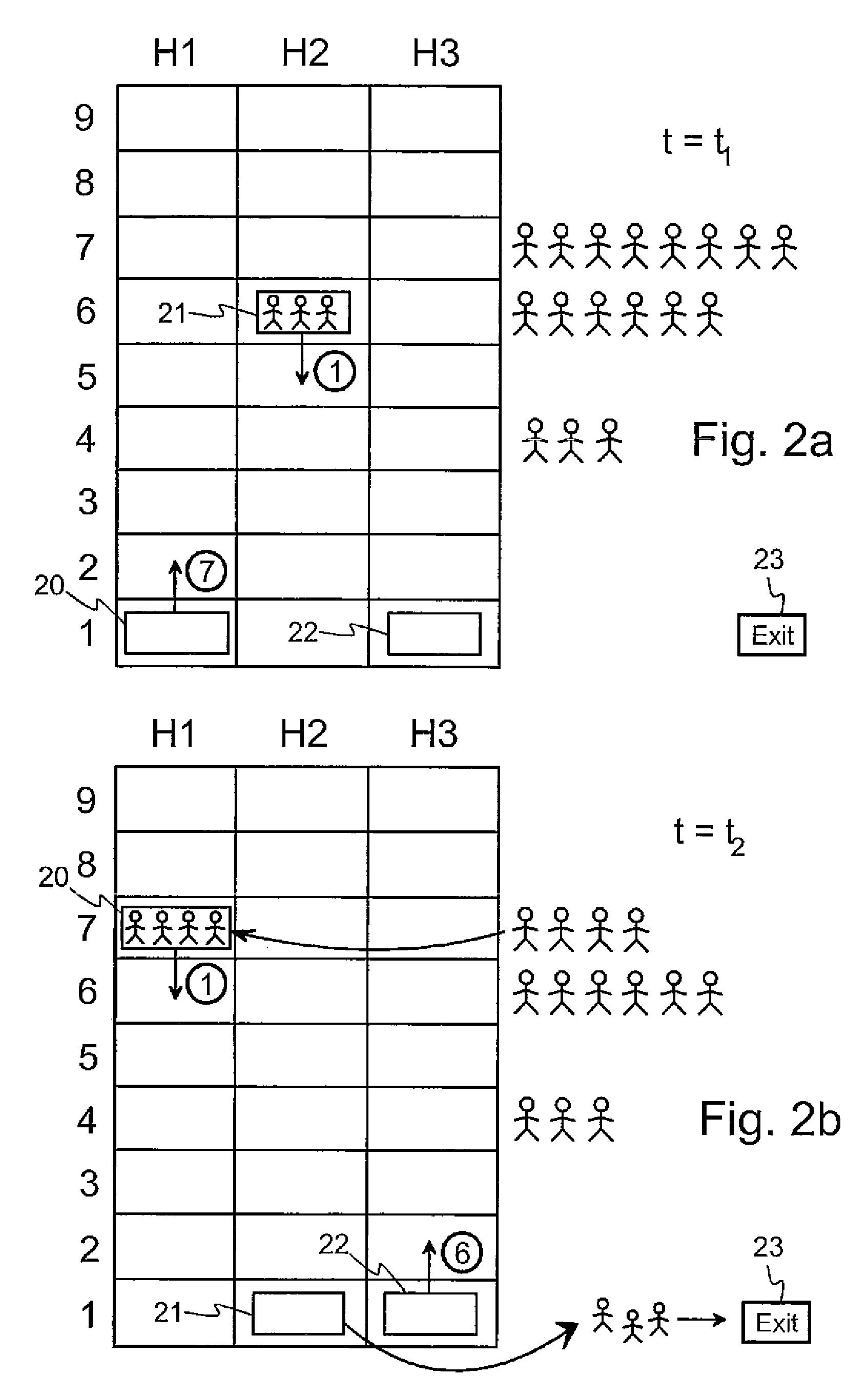
[0043]The present invention discloses a method for effective evacuation of a building using the elevators of the building. It can be assumed that the building contains elevators and stairways as well as travelators, or only some of these types of conveyance. If the building to be monitored is high-rise, it can contain both shuttle elevators and so-called local elevators. Shuttle elevators are intended for longer floor-to-floor distances in a high-rise building such that a shuttle elevator serves only e.g. the upper floors of a high-rise building. In this case from the lobby floor it is only possible to go to the desired upper floor and vice versa. This enables fast elevator service on the upper floors of a high-rise building.

[0044]It must be noted that shuttle elevators consume more power than so-called conventional elevators.

[0045]In addition to shuttle elevators, so-called local elevators are needed, with which the other floors of a high-rise building are served. In this case inte...


PUM


Abstract

The present invention discloses a method, a system and a computer program for the effective evacuation of a building in an emergency, in which at least one elevator can be used as an evacuation aid. In the method the group control of the elevators monitors the numbers of people on the different floors of the building. The floor on which it is assumed are most people is set at each moment of monitoring for a greater priority in an evacuation situation. Taking into account the limited supply power a free elevator car is directed to the floor of the greatest priority, at which the elevator is filled. The full elevator is directed without stopping to the exit floor of the building. The system monitors by means of detectors the safety of the different parts of the building and directs people if necessary to a safe evacuation location to wait for an elevator. A so-called Traffic Forecaster can be used as an aid in defining the priorities.

Description

[0001]This application is a Continuation of copending PCT International Application No. PCT / FI2007 / 000040 filed on Feb. 19, 2007, which designated the United States, and on which priority is claimed under 35 U.S.C. § 120. This application also claims priority under 35 U.S.C. § 119(a) on Patent Application No(s). 20060215 filed in Finland on Mar. 3, 2006. The entire contents of each of the above documents is hereby incorporated by reference.FIELD OF THE INVENTION[0002]The present invention relates to elevator systems and especially to the control of elevators in a situation in which a building is evacuated with the aid of the elevators and in which the elevator system is dependent on an emergency power source.BACKGROUND OF THE INVENTION[0003]The allocation of calls given by elevator users to the different elevators of the elevator system is one of the basic tasks of the control of the system. The purpose of allocation is to give calls for the elevator cars to serve such that one of t...

Claims


Application Information

Patent Timeline
Patent Type & Authority Patents(United States)
IPC IPC(8): B66B1/20
CPCB66B5/021B66B5/024B66B5/022B66B1/18
Inventor SIIKONEN, MARJA-LIISASORSA, JANNESARJANEN, JUKKA-PEKKABARLUND, KIM
Owner KONE CORP
Why Eureka
Try Eureka