Medium feeding apparatus, liquid ejecting apparatus and recording apparatus

a technology of liquid ejecting apparatus and feeding apparatus, which is applied in the field of medium feeding, can solve the problems of paper jam, paper feeding failure in the feed of paper, and the contact between the two sides of paper, and achieve the effect of removing frictional resistan

Inactive Publication Date: 2009-09-29
SEIKO EPSON CORP
View PDF27 Cites 5 Cited by
  • Summary
  • Abstract
  • Description
  • Claims
  • Application Information

AI Technical Summary

Benefits of technology

[0008]An advantage of some aspects of the invention is to provide a medium feeding apparatus capable of eliminating a frictional resistance between both side ends of a medium to be fed and each guide unit when feeding the medium to be fed, a liquid ejecting apparatus including the medium feeding apparatus, and a recording apparatus.
[0010]A first aspect of the invention is to provide a medium feeding apparatus comprising: a pivot unit, supporting a medium and pivoting to cause the medium to come in contact with and to separate from a feeding unit; a first guide unit, guiding one side end of the medium supported on the pivot unit; a second guide unit, guiding the other side end of the medium; a first moving unit, moving the first guide unit to come in contact with and to separate from the one side end of the medium in conjunction with the pivoting motion of the pivot unit; and a second moving unit, moving the second guide unit to come in contact with and to separate from the other side end of the fed medium in conjunction with the movement of the first guide unit. For example, consequently, both side ends and each guide unit can be caused to come in contact with each other in the non-feed of the medium to be fed and the initial stage of the feed, and the guide unit can be separated from both side ends in the latter stage of the feed of the medium to be fed. Therefore, it is possible to eliminate a frictional resistance between both side ends and the guide unit in the latter stage of the feed of the medium to be fed.
[0011]Moreover, the invention may be characterized in that the pivot unit is also moved with the movement of the first guide unit. Consequently, it is possible to separately constitute an automatic moving mechanism of the first guide unit by the first moving unit and a manual moving mechanism of the first guide unit by a user. Moreover, the first moving unit may be characterized by a guide protruded portion and a guide groove to be engaged with the guide protruded portion. The guide groove may be characterized by a straight groove formed on the side of the feeding unit extended in a pivoting direction of the pivot unit and an inclined groove formed on an opposite side to the feeding unit inclined with respect to the straight groove. Consequently, the first moving unit to be in conjunction with the pivoting motion of the pivot unit can have a simple structure. Moreover, the second moving unit may be characterized by a pair of pinion gears and a pair of rack gears to be engaged with the pinion gears. The invention is characterized in that the pinion gears may be attached to the pivot unit and the rack gears may be attached to the second moving unit. Consequently, the second moving unit to be in conjunction with the movement of the first guide unit can have a simple structure.
[0013]Moreover, a third aspect of the invention is to provide a recording apparatus for carrying out recording over a medium to be recorded and comprises any of the medium feeding apparatuses. Consequently, it is possible to provide a medium feeding apparatus or a recording apparatus which can produce each of the functions and advantages.

Problems solved by technology

For this reason, in the case in which the gap is large, there is a possibility that the paper might be inclined in the feed of the paper, causing a paper jam.
In the case in which the gap is small, there is a possibility that a frictional resistance (a back tension) between each side end of the paper and each guide might be increased to generate a paper feeding failure in the feed of the paper.
For this reason, there is a possibility that the paper might become loose due to a friction between the papers or a vibration in a recording operation, causing both side ends of the paper to come in contact with the fixed guide and the moving guide.
When such a contact is generated, a frictional resistance (a back tension) between both side ends of the paper and the fixed guide and moving guide is increased in the feed of the paper so that the paper feeding failure is generated.
In a recording operation in the latter stage of the paper feed, particularly, there is a possibility that recording precision might be deteriorated.

Method used


Image

  • Medium feeding apparatus, liquid ejecting apparatus and recording apparatus
  • Medium feeding apparatus, liquid ejecting apparatus and recording apparatus
  • Medium feeding apparatus, liquid ejecting apparatus and recording apparatus

Examples


Embodiment Construction

[0029]An embodiment according to the invention will be described with reference to the drawings. The embodiment which will be described below is not restricted to the invention according to the claims and all of combinations of the features described in the embodiment are not always essential to the means for solution according to the invention.

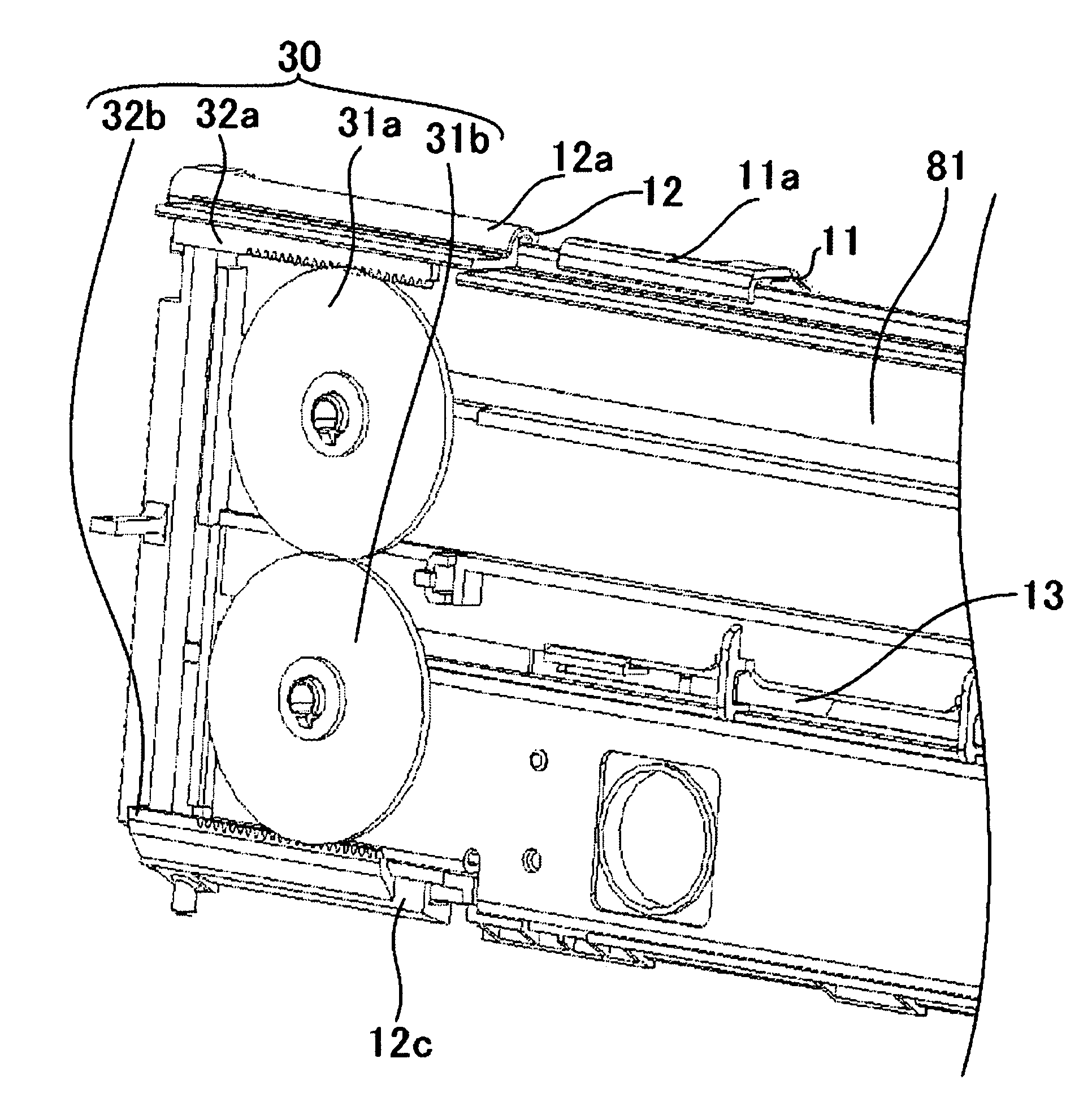
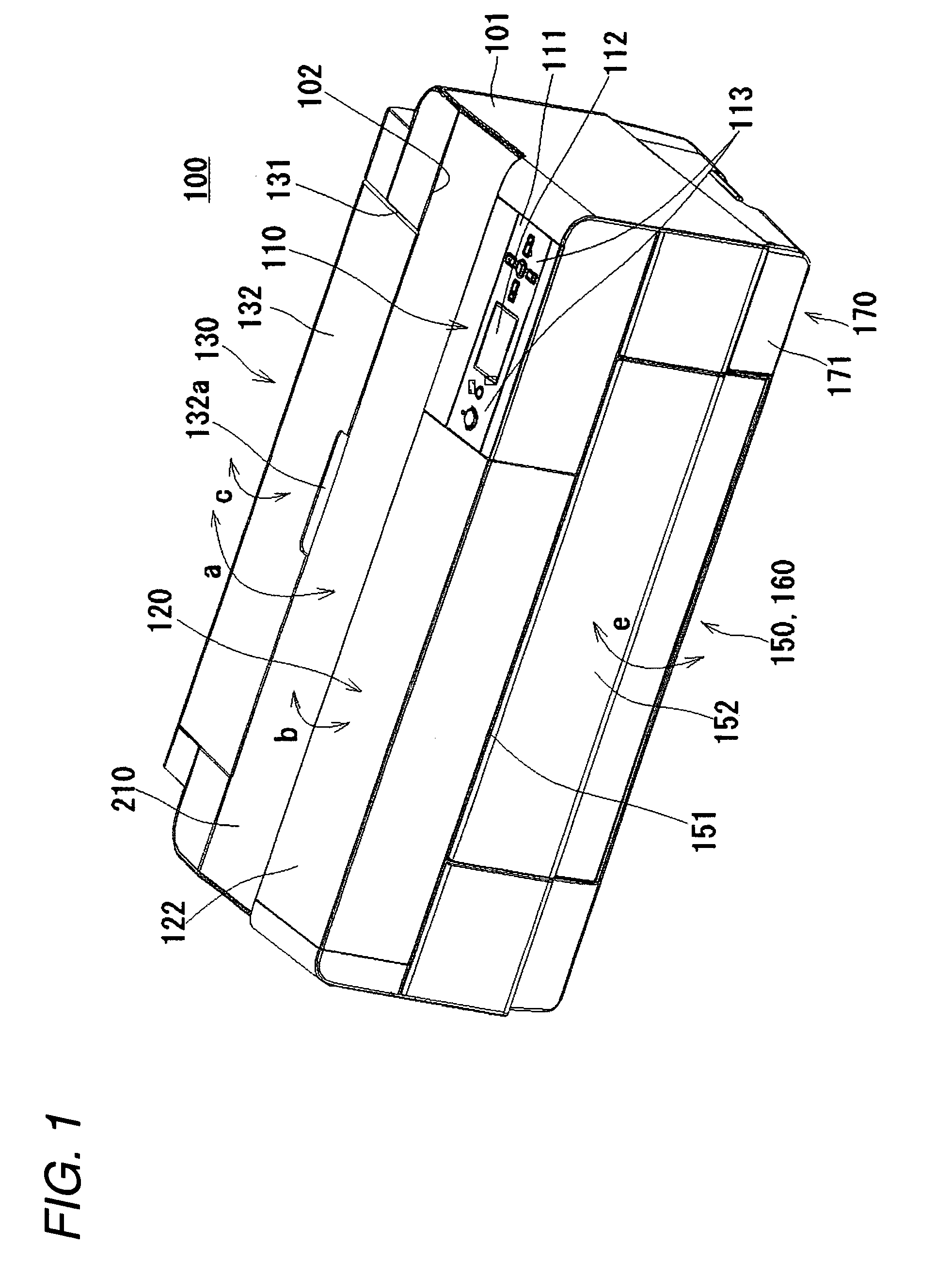
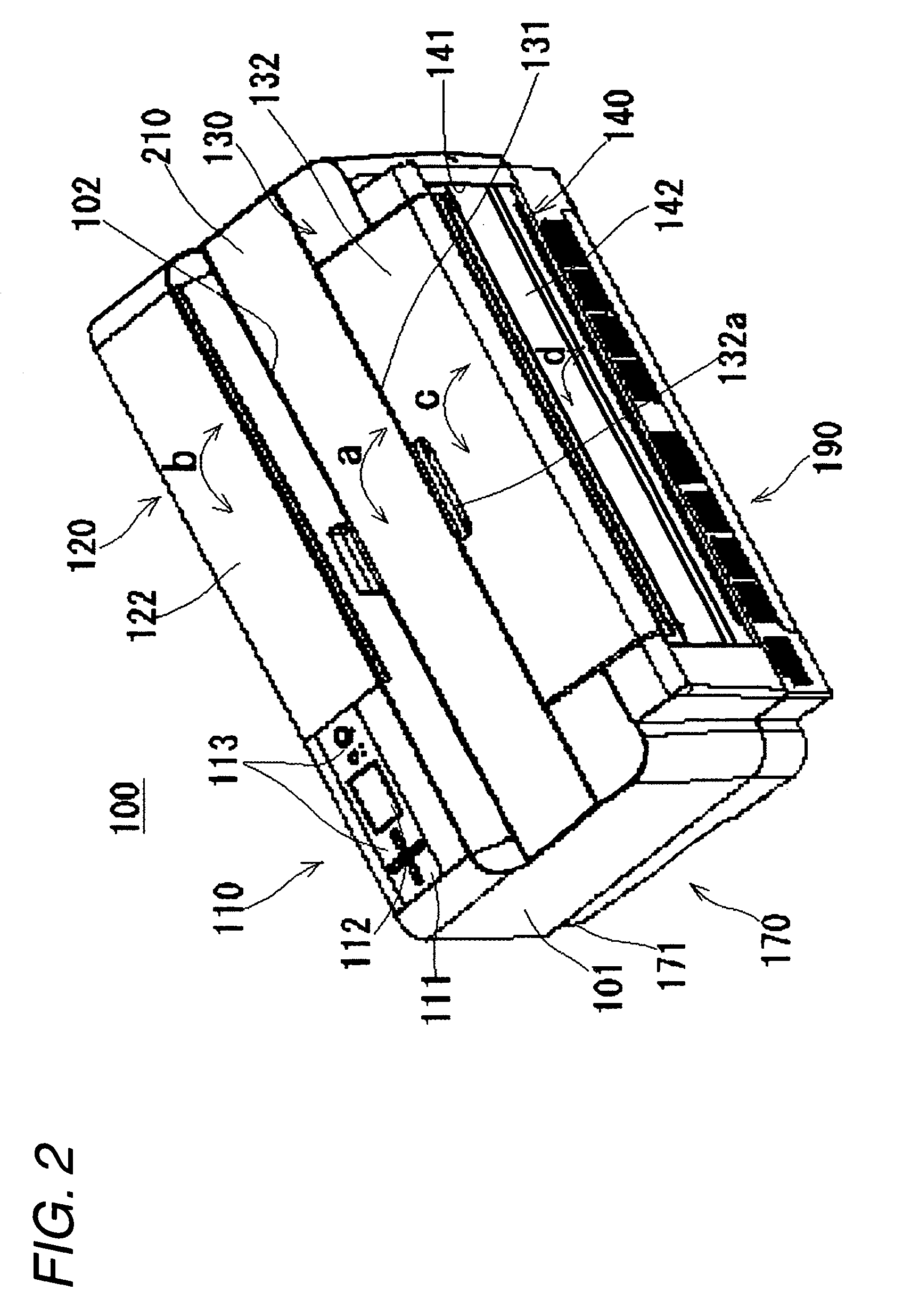
[0030]FIGS. 1 and 2 are perspective views showing a whole structure of an appearance of a printer of an ink jet type to be one of recording apparatuses according to an embodiment of the invention as seen obliquely from front and rear parts, FIG. 3 is a perspective view schematically showing an internal structure thereof, and FIG. 4 is a sectional side view schematically showing the internal structure thereof. A printer 100 of an ink jet type has a function capable of carrying out recording, with an ink (a liquid), over a cut-form paper having a size such as an L size / 2L size, a postcard, or an A4, A3 extension or A2 size on the JIS (hereinaft...


PUM

PropertyMeasurementUnit
thicknessaaaaaaaaaa
thicknessaaaaaaaaaa
thicknessaaaaaaaaaa

Abstract

A medium feeding apparatus includes: a pivot unit, supporting a medium and pivoting to cause the medium to come in contact with and to separate from a feeding unit; a first guide unit, guiding one side end of the medium supported on the pivot unit; a second guide unit, guiding the other side end of the medium; a first moving unit, moving the first guide unit to come in contact with and to separate from the one side end of the medium in conjunction with the pivoting motion of the pivot unit; and a second moving unit, moving the second guide unit to come in contact with and to separate from the other side end of the fed medium in conjunction with the movement of the first guide unit.

Description

BACKGROUND[0001]1. Technical Field[0002]The present invention relates to a medium feeding apparatus for feeding a medium to be fed, a liquid ejecting apparatus including the medium feeding apparatus, and a recording apparatus.[0003]2. Related Art[0004]In a printer of an ink jet type to be one of general recording apparatuses, an automatic paper feeding apparatus is provided in an upper part on a back side. The automatic paper feeding apparatus comprises a hopper for supporting a paper together with a paper support and a paper feeding roller disposed opposite to the hopper and serving to feed the paper which is supported. A guide for regulating a support position of the paper and guiding the feed of the paper is attached to the hopper. Two guides are provided to carry out the regulation and the guide in contact with both side ends of the paper, respectively. One of the guides serves as a fixing guide fixed to the hopper and the other guide serves as a moving guide for being slid in a...

Claims


Application Information

Patent Timeline
Patent Type & Authority Patents(United States)
IPC IPC(8): B65H1/00
CPCB41J13/103B65H3/0607B65H3/0661B65H9/04B65H2404/742B65H2301/42344B65H2402/31B65H2403/512B65H2404/741B65H2301/42328B41J13/00B41J11/00
Inventor SHIOHARA, HIROSHIKATO, JUNYANAGASHIMA, YUTAKA
Owner SEIKO EPSON CORP
Why Eureka
Try Eureka