Double-chain reversing oil pumping method and oil pumping unit

A technology of double chain and pumping unit, which is applied in the direction of earthwork drilling, production fluid, wellbore/well components, etc., which can solve the problems of special chain link fatigue damage, increased risk of equipment fatigue damage, and additional alternating stress. and other problems, to achieve the effect of eliminating additional alternating stress, reducing equipment adjustment time, and reducing failure rate and maintenance rate

Inactive Publication Date: 2014-03-26
WENZHOU HUSITE ENVIRONMENTAL PROTECTION EQUIP
View PDF4 Cites 1 Cited by
  • Summary
  • Abstract
  • Description
  • Claims
  • Application Information

AI Technical Summary

Problems solved by technology

At present, there are many belt pumping units with single-chain transmission in the market. With single-sprocket transmission, under the drive of the motor, the sprocket drives the chain to make a circular circular motion, and the commutation is realized through special chain links. Reciprocating up and down, this reversing structure is easily damaged. In addition, the lifting force of the single chain pumping unit to support the counterweight box deviates from the center of gravity of the counterweight, which will generate a pair of force couples PR in the vertical plane, resulting in the inclination of the counterweight box. Increase the load of the centering wheel, so that the centering wheel is often worn due to extrusion, which increases the failure maintenance rate. Another potential hidden danger of single chain transmission is the increased risk of fatigue damage to the equipment. On the chain link shaft, additional stress is generated. Since the special chain link must perform lateral periodic movement between the two chains when the reciprocating frame reverses up and down, the additional stress is an alternating stress. When the lifting force passes through the center of gravity of the counterweight, the additional stress is zero, when the lifting force passes through the center line of the chain, the additional stress is the largest
Since the shaft diameter of the special chain link is less than 100mm, the impact of the additional alternating stress is relatively large, and the stress of the next motion cycle changes four times, so the impact on the fatigue damage of the special chain link is quite large, and it has become a guarantee for equipment safety. a hidden danger
After the single chain pumping unit has been in operation for two years, the side centralizing wheel is squeezed and damaged, the guide rail surface of the column is worn through, and even the centering wheel is damaged and the side of the column (that is, the guide rail surface) is worn through.

Method used


Image

  • Double-chain reversing oil pumping method and oil pumping unit
  • Double-chain reversing oil pumping method and oil pumping unit
  • Double-chain reversing oil pumping method and oil pumping unit

Examples


Embodiment 1

[0039] refer to Figure 1 to Figure 7 ,Such as Figure 1 to Figure 7 A kind of double-chain reversing oil pumping method shown, comprises the following steps:

[0040] Step S10, the motor 40 drives the reducer 30 to rotate through the belt, so that the driving output shaft 31 and the driven output shaft 33 rotate;

[0041] Step S11, the driving output shaft 31 and the driven output shaft 33 simultaneously drive the chain 83 and the reversing mechanism 90 to form continuous motion;

[0042] Step S12, the reversing mechanism 90 drives the reciprocating frame 85 to move up and down;

[0043] Step S13, the reciprocating frame 85 drives the traction belt 60 to move up and down;

[0044] Step S14, the traction belt 60 drives the wire suspension rope 70 to move up and down through the first belt roller 55 and the second belt roller 56;

[0045] In step S15, the front end of the steel wire suspension rope 70 is connected to the sucker rod to realize the up and down reciprocating m...

Embodiment 2

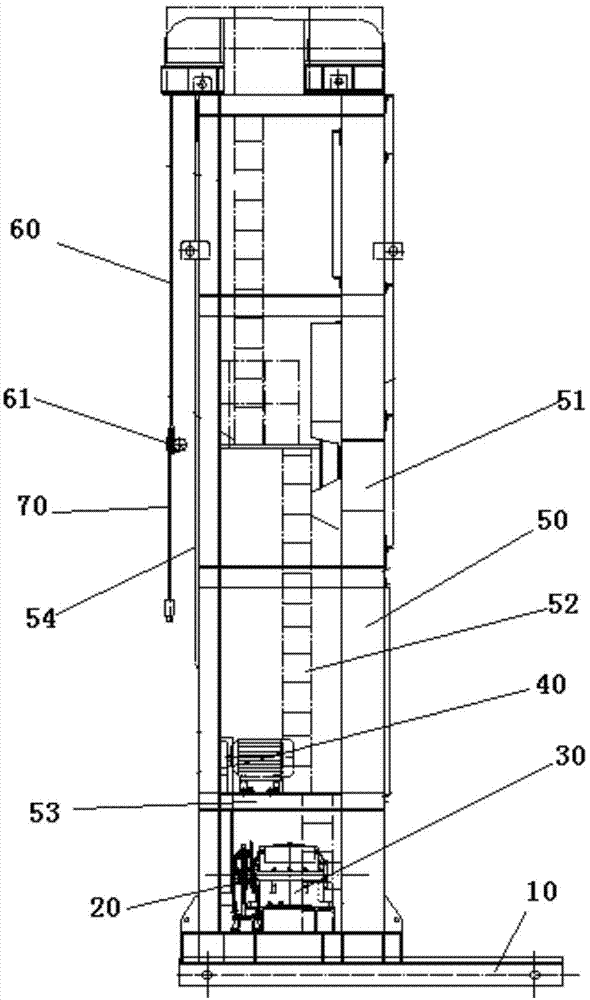
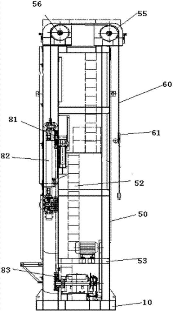
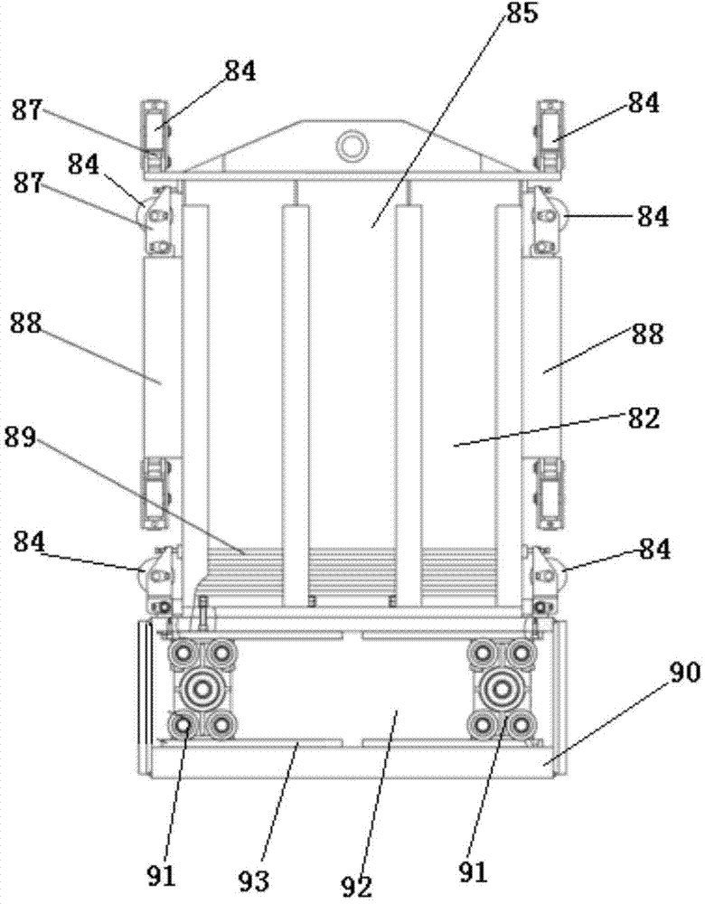
[0049] refer to Figure 1 to Figure 7 ,Such as figure 1 The shown double chain reversing pumping unit includes a base 10 and a tower 50 arranged on the base 10, wherein the top of the tower 50 is provided with a first belt roller 55 and a second belt roller parallel to each other 56, the first belt roller 55 and the second belt roller 56 balance and support the traction belt 60, so that the force on the tower 50 is balanced, and the tower 50 is provided with two sets of lower sprockets 81 and two sets of upper sprockets 86, The lower sprocket 81 and the upper sprocket 86 are provided with a chain 83, one side of the tower 50 is provided with a reciprocating frame 85, and the bottom of the reciprocating frame 85 is provided with a reversing mechanism 90, and the reversing mechanism 90 is provided with The reversing wheel group 91, the reversing wheel group 91 is provided with the chain link 914 that is connected with the chain 83, and the traction belt 60 is connected to the top...


PUM


Abstract

The invention discloses a double-chain reversing oil pumping method and an oil pumping unit using the method. The method includes the following steps that step 10, rotational motion of a motor is output through two shafts driven by a speed reducer; step 11, the two shafts drive a reversing mechanism to form long ring continuous motion through transmission of chains; step 12, the reversing mechanism drives a shuttling frame to move up and down, the shuttling frame drives a traction belt to move up and down, and thus a sucker rod is driven to make reciprocating motion vertically. The invention further comprises the double-chain reversing oil pumping unit. The oil pumping unit comprises a base and a tower arranged on the base. A first belt roller and a second belt roller which are parallel with each other are arranged on the top of the tower, two sets of lower chain wheels and two sets of upper chain wheels are arranged on one side of the tower, the traction belt is connected to the upper portion of the shuttling frame, and the traction belt stretches to the other side of the tower through the first belt roller and the second belt roller. The oil pumping unit has the advantages of being simple in structure, low in cost, high in efficiency, convenient to use, stable in reversing, safe, high in efficiency and the like.

Description

technical field [0001] The invention relates to a pumping unit and method for oil recovery in an oil field, in particular to a double-chain reversing oil pumping method and the pumping unit. Background technique [0002] At present, the chain-belt pumping unit is a low-stroke, long-stroke, and heavy-duty surface oil production equipment that can meet oil wells in various working conditions. It has the characteristics of high efficiency, safety, reliability, and energy saving. There are a wide range of applications. At present, there are many belt pumping units with single-chain transmission in the market. With single-sprocket transmission, under the drive of the motor, the sprocket drives the chain to make a circular circular motion, and the commutation is realized through special chain links. Reciprocating up and down, this reversing structure is easily damaged. In addition, the lifting force of the single chain pumping unit to support the counterweight box deviates from t...

Claims


Application Information

Patent Timeline
Patent Type & Authority Applications(China)
IPC IPC(8): E21B43/00
Inventor 吴涌
Owner WENZHOU HUSITE ENVIRONMENTAL PROTECTION EQUIP
Why Eureka
Try Eureka