Blower

A blower and rotating disc technology, which is applied in mechanical equipment, engine manufacturing, machine/engine, etc., can solve the problems of limited motor configuration position, waste of inner space, and decreased space efficiency, so as to achieve compact structure of rotating support and eliminate frictional resistance , the effect of improving life

Active Publication Date: 2021-11-19
LG ELECTRONICS INC
View PDF8 Cites 0 Cited by
  • Summary
  • Abstract
  • Description
  • Claims
  • Application Information

AI Technical Summary

Problems solved by technology

[0004] However, the conventional air blower has a problem that, when a structure for improving the air blowing performance and filtering performance of the air blower is additionally arranged in the main body, there is no durable bearing capable of supporting the increased load. structure
[0005] In addition, the conventional air blower also has a problem that, in order to avoid interference with the rotating disk, the arrangement position of the motor for rotating the main body is limited.
[0006] Korean Patent No. 10-1814574 discloses a bearing structure that supports the rotation of the blower and a motor that is arranged on the base to provide rotational force. However, since the bearing is arranged at the center of the main body, it cannot evenly support the main body scattered radially outward. The problem point of the load
In addition, the inner space of the ring-shaped bearing is wasted, and in order to avoid interference with the bearing and the rotating disk, the motor can only be installed on the base, so there is a problem that the space efficiency is reduced.
In addition, since a sufficient separation distance is not ensured between the non-rotating structure and the rotating structure in the fan, there is a possibility that the life of the bearing and the main body will be shortened due to the friction generated between the structures due to the rotation. question
[0007] Korean Patent No. 10-1370267 discloses a bearing structure that supports a shaft to rotate smoothly inside a sleeve, but only supports the rotation of the shaft and does not describe a structure that supports the entire load of the main body

Method used


Image

  • Blower
  • Blower
  • Blower

Examples


Embodiment Construction

[0100] The advantages, features, and methods for realizing the present invention can be clarified more clearly by referring to the accompanying drawings and the embodiments described in detail later. However, the present invention is not limited to the embodiments disclosed below, but can be realized in various forms. This embodiment is only for more complete disclosure of the present invention, so as to clarify to those of ordinary skill in the technical field to which the present invention belongs. The scope of the present invention is fully shown, and the present invention is defined only by the scope of the claims. Throughout the specification, the same reference numerals denote the same structural elements.

[0101] Hereinafter, the present invention will be described with reference to drawings for explaining blowers based on embodiments of the present invention.

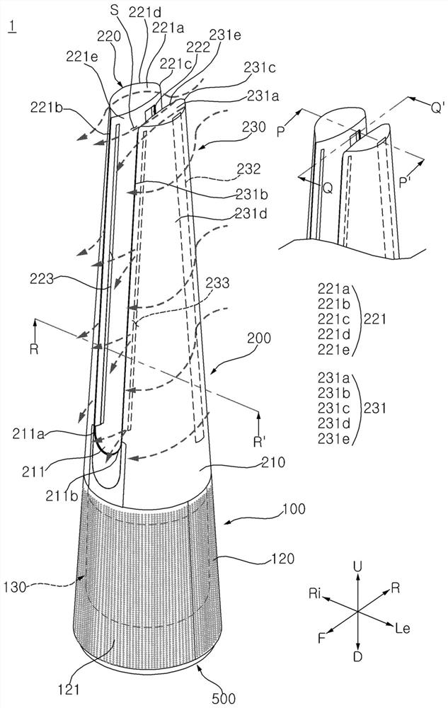
[0102] First, refer to figure 1 The overall structure of the air blower 1 will be described. figure 1 The...


PUM


Abstract

The invention relates to a blower. The blower comprises a base; a housing disposed on the upper side of the base and having an air inlet and an air outlet formed therein; a fan disposed inside the housing; a rotating disk connected to the housing and rotatably disposed on an upper side of the base; a motor for generating power for rotating the rotating disk; and a bearing which is disposed between the rotating disk and the base, is fixed to the rotating disk, and is movably supported by the base. As the bearing disposed on the rotating disk is supported on the base and rotates, the rotation of the blower is stably supported by the base and the bearing.

Description

technical field [0001] The present invention relates to a blower, and more specifically relates to a blower rotation structure. Background technique [0002] Blowers work by creating a flow of air that circulates the air in the interior space or creates an airflow that flows toward the user. When the blower is provided with a filter, the blower can improve indoor air quality by purifying polluted air in the room. [0003] In order to adjust the wind direction of the air discharged from the blower, it is necessary to rotate the main body of the blower, and the blower may be provided with a bearing supporting the rotation of the main body. [0004] However, the conventional air blower has a problem that, when a structure for improving the air blowing performance and filtering performance of the air blower is additionally arranged in the main body, there is no durable bearing capable of supporting the increased load. structure. [0005] In addition, the conventional air blow...

Claims


Application Information

Patent Timeline
Patent Type & Authority Applications(China)
IPC IPC(8): F04F5/16F04F5/44
CPCF04F5/16F04F5/44F04D25/10F04D29/703F04D29/582F04D29/524F04D25/14F05D2250/411Y02B30/70F04D25/08F04D29/403
Inventor 金宰贤郑惠仁朴欣喜金容民白承浩金起东崔硕浩朴亨镐金厚辰吴时荣张皓植崔致英
Owner LG ELECTRONICS INC
Why Eureka
Try Eureka