Brush-less type rotation detector shielding structure

a shielding structure and rotation detector technology, applied in the direction of instruments, dynamo-electric components, continuously variable inductance/transformers, etc., can solve the problem and achieve the effect of reducing the angle detection accuracy of the rotation detector

Inactive Publication Date: 2009-09-29
TAMAGAWA SEIKI CO LTD
View PDF13 Cites 0 Cited by
  • Summary
  • Abstract
  • Description
  • Claims
  • Application Information

AI Technical Summary

Benefits of technology

[0004]A general conventional brushless type rotation detector is reliable. However, a rotation transformer used has a gap, which causes leakage of magnetic flux, and the magnetic flux interferes with a stator iron core or a rotor iron core to reduce angle detection accuracy of the rotation detector.
[0005]An object of the present invention is to provide a shielding structure for a brushless type rotation detector capable of solving the problem of the above described conventional technique, reducing interference of magnetic flux leaking from a rotation transformer with a stator iron core or a rotor iron core, and restraining a reduction in angle detection accuracy.
[0015]Specifically, according to the present invention, a magnetic shielding plate is provided between the rotation transformer and the stator iron core to reduce interference of magnetic flux leaking from the rotation transformer with the stator iron core or the rotor iron core, and restrain a reduction in angle detection accuracy of the brushless type rotation detector.
[0016]The shielding structure for a brushless type rotation detector according to the present invention is configured as described above. This reduces interference of magnetic flux leaking from the rotation transformer with the stator iron core or the rotor iron core, and restrains a reduction in angle detection accuracy.

Problems solved by technology

However, a rotation transformer used has a gap, which causes leakage of magnetic flux, and the magnetic flux interferes with a stator iron core or a rotor iron core to reduce angle detection accuracy of the rotation detector.

Method used


Image

  • Brush-less type rotation detector shielding structure
  • Brush-less type rotation detector shielding structure
  • Brush-less type rotation detector shielding structure

Examples


Embodiment Construction

[0023]Now, the present invention will be described in detail with reference to the drawings.

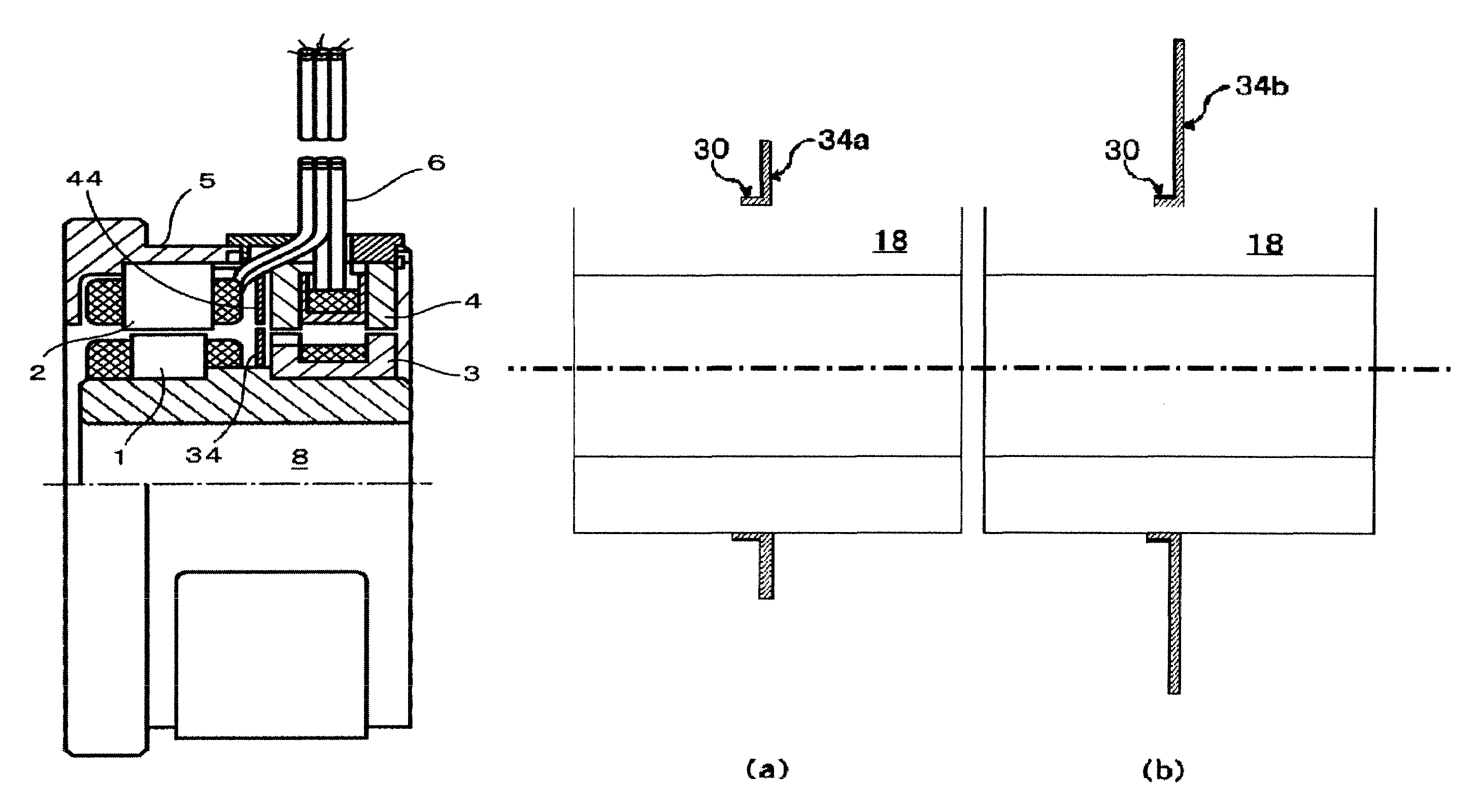
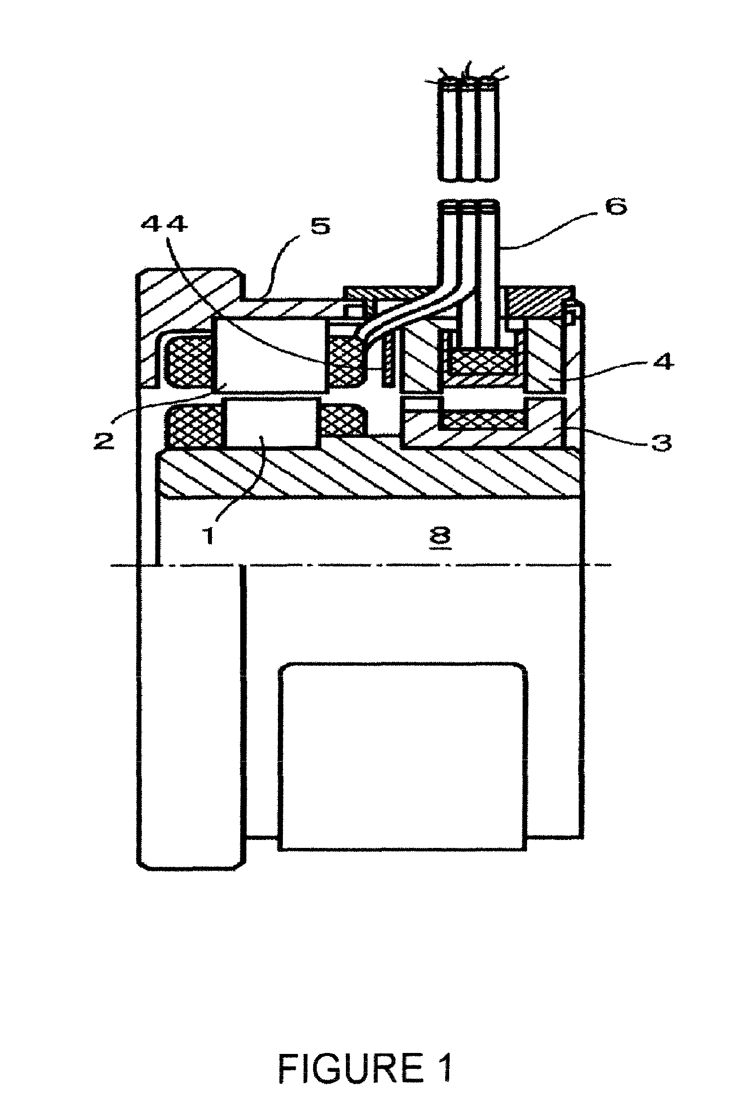
[0024]FIG. 1 is a half section showing a configuration of a shielding structure for a brushless type rotation detector according to the present invention taking a brushless resolver as an example. In the figure, the shielding structure is a shielding structure for a brushless type rotation detector including a signal modulation section including a rotation transformer constituted by a rotor transformer 3 and a stator transformer 4, a stator iron core 2, and a rotor iron core 1, for modulating an output voltage induced by an excitation voltage according to a rotation angle to be detected, and a case 5 that houses the signal modulation section, wherein the shielding structure includes a stator magnetic shielding section 44 that provides a magnetic shield between the stator iron core 2 and the stator transformer 4 that constitute the signal modulation section.

[0025]In the figure, with such a con...


PUM


Abstract

It is possible to provide a brush-less type rotation detector shielding structure capable of reducing the interference of magnetic flux leaking from a rotation transformer to a stator iron core and rotor iron core and suppressing lowering of the angle detection accuracy. As shown in FIG. 1, the shielding structure is used for a brush-less type rotation detector including: a rotation transformer having a rotor transformer (3) and stator transformer (4); a signal modulation section having a stator iron core (2) and a rotor iron core (1); and a case (5) for containing them. The shielding structure has a main configuration having a stator magnetic shielding section (44) capable of magnetically shielding between the stator iron core (2) constituting the signal modulation section and the stator transformer (4).

Description

TECHNICAL FIELD[0001]The present invention relates to a shielding structure for a brushless type rotation detector for detecting a rotation angle of a rotary machine, and more particularly, to a shielding structure for a brushless type rotation detector capable of reducing interference of magnetic flux leaking from a rotation transformer with a stator iron core or a rotor iron core, and restraining a reduction in angle detection accuracy.BACKGROUND ART[0002]Brushless type rotation detectors such as brushless resolvers or brushless synchros transmit signals using a rotation transformer constituted by a stator transformer and a rotor transformer instead of a brush.[0003]FIG. 5 is a half section showing a structure for a brushless resolver as an example of a conventional brushless type rotation detector. In the figure, the conventional brushless resolver includes a signal modulation section (constituted by 51 and 52, or the like described later) for modulating an output voltage induced...

Claims


Application Information

Patent Timeline
Patent Type & Authority Patents(United States)
IPC IPC(8): H02K24/00G01D5/245H02K11/00H02K29/08
CPCH02K29/08H02K11/0005H02K11/012H02K11/014
Inventor TAGAWA, HIROSHI
Owner TAMAGAWA SEIKI CO LTD
Why Eureka
Try Eureka