
Method of gain error calibration in a pipelined analog-to-digital converter or a cyclic analog-to-digital converter

a technology of analog-to-digital converter and gain error calibration, which is applied in the field of analog-to-digital converter gain error calibration, can solve the problems of increasing circuit complexity and chip area, error in the stage output value of all subsequent stages, and deviating from the predetermined gain value of each stag

Inactive Publication Date: 2009-09-29
MEDIATEK INC
View PDF4 Cites 8 Cited by
  • Summary
  • Abstract
  • Description
  • Claims
  • Application Information

AI Technical Summary

Benefits of technology

The invention provides methods for calibrating gain errors in pipelined and cyclic analog-to-digital converters (ADCs). The methods involve generating correction numbers, collecting stage output values, and correlating them with the correction numbers to estimate gain error estimates. These estimates are then weighted to obtain a predicted gain error for each stage. The technical effect of the invention is to improve the accuracy and reliability of analog-to-digital conversion in pipelined and cyclic ADCs.

Problems solved by technology

When the required resolution of a digital output signal increases, a flash ADC must include a great number of comparators, increasing circuit complexity and chip area thereof.
However, the actual gain value of each stage often deviates from the predetermined gain value due to chip fabrication errors or rise in chip temperature.
A gain error makes a preceding stage generate a mis-amplified stage output signal, causing errors in the stage output values of all subsequent stages in the series.
If the number of collected samples is reduced, a low precision gain error estimate results.
If the number of the collected samples is increased, the time required for collecting samples causes latency in gain error estimation.

Method used


Image

  • Method of gain error calibration in a pipelined analog-to-digital converter or a cyclic analog-to-digital converter
  • Method of gain error calibration in a pipelined analog-to-digital converter or a cyclic analog-to-digital converter
  • Method of gain error calibration in a pipelined analog-to-digital converter or a cyclic analog-to-digital converter

Examples


Embodiment Construction

[0024]The following description is of the best-contemplated mode of carrying out the invention. This description is made for the purpose of illustrating the general principles of the invention and should not be taken in a limiting sense. The scope of the invention is best determined by reference to the appended claims.

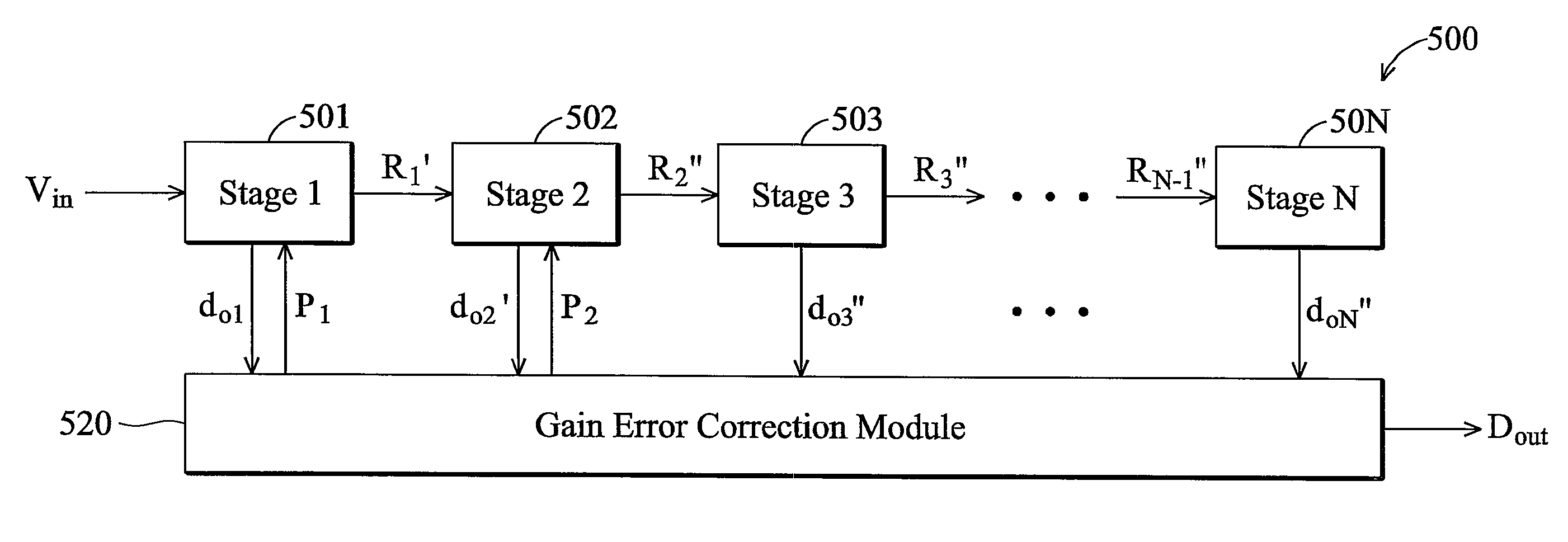
[0025]FIG. 5 shows a process for estimating a gain error of a first stage 501 and a second stage 502 of a pipelined ADC 500 according to the invention, wherein the first stage 501 and a second stage 502 share a common operational amplifier. The first stage 501 and a second stage 502 use the common amplifier to generate the stage output signals R1′ and R2″. Although the first stage 501 and the second stage 502 have the same gain error, a gain error correction module 520 still respectively calculates a gain error estimate ε1 of the first stage 501 and a gain error estimate ε2 of the second stage 502. The gain error correction module 520 then weights the gain error estima...


PUM


Abstract

The invention provides a method of gain error calibration in a pipelined analog-to-digital converter (ADC). In one embodiment, a first stage and a second stage of the pipelined ADC share a common operational amplifier. The first stage is requested to generate the stage output signal thereof according to a first correction number. The second stage is also requested to generate the stage output signal thereof according to a second correction number. A plurality of stage output values generated by stages of the pipelined ADC are collected. The stage output values are respectively correlated with the first correction number and the second correction number to estimate a first gain error estimate of the first stage and a second gain error estimate of the second stage. The first gain error estimate and the second gain error estimate are weighted to obtain a predicted gain error for gain error calibration in the first stage and the second stage.

Description

CROSS REFERENCE TO RELATED APPLICATIONS[0001]This application claims the benefit of U.S. Provisional Application No. 60 / 951,255, filed on Jul. 23, 2007.BACKGROUND OF THE INVENTION[0002]1. Field of the Invention[0003]The invention relates to analog-to-digital converters (ADC), and more particularly to gain error calibration of ADCs.[0004]2. Description of the Related Art[0005]An analog-to-digital converter converts an analog input signal to a digital output signal. Analog-to-digital converters are classified into several categories including flash ADCs, pipelined ADCs, and cyclic ADCs. Among the three ADC categories, a flash ADC has the shortest latency, because it has the simplest circuit structure. A flash ADC comprises multiple comparators directly comparing an analog input signal with multiple reference voltages to generate a digital output signal. When the required resolution of a digital output signal increases, a flash ADC must include a great number of comparators, increasing...

Claims


Application Information

Patent Timeline
Patent Type & Authority Patents(United States)
IPC IPC(8): H03M1/06
CPCH03M1/1019H03M1/44H03M1/40
Inventor TU, YU-HSUAN
Owner MEDIATEK INC
Learn More