Parametric array modulation and processing method

a processing method and array technology, applied in the field of parametric array modulation and processing methods, can solve the problem that the residual sound generated by the envelope signal should be inaudibl

Active Publication Date: 2009-09-29
POMPEI FRANK JOSEPH
View PDF9 Cites 24 Cited by
  • Summary
  • Abstract
  • Description
  • Claims
  • Application Information

AI Technical Summary

Problems solved by technology

In addition, residual sound generated by the envelope signal should be inaudible in the resulting demodulated beam.

Method used


Image

  • Parametric array modulation and processing method
  • Parametric array modulation and processing method
  • Parametric array modulation and processing method

Examples


Embodiment Construction

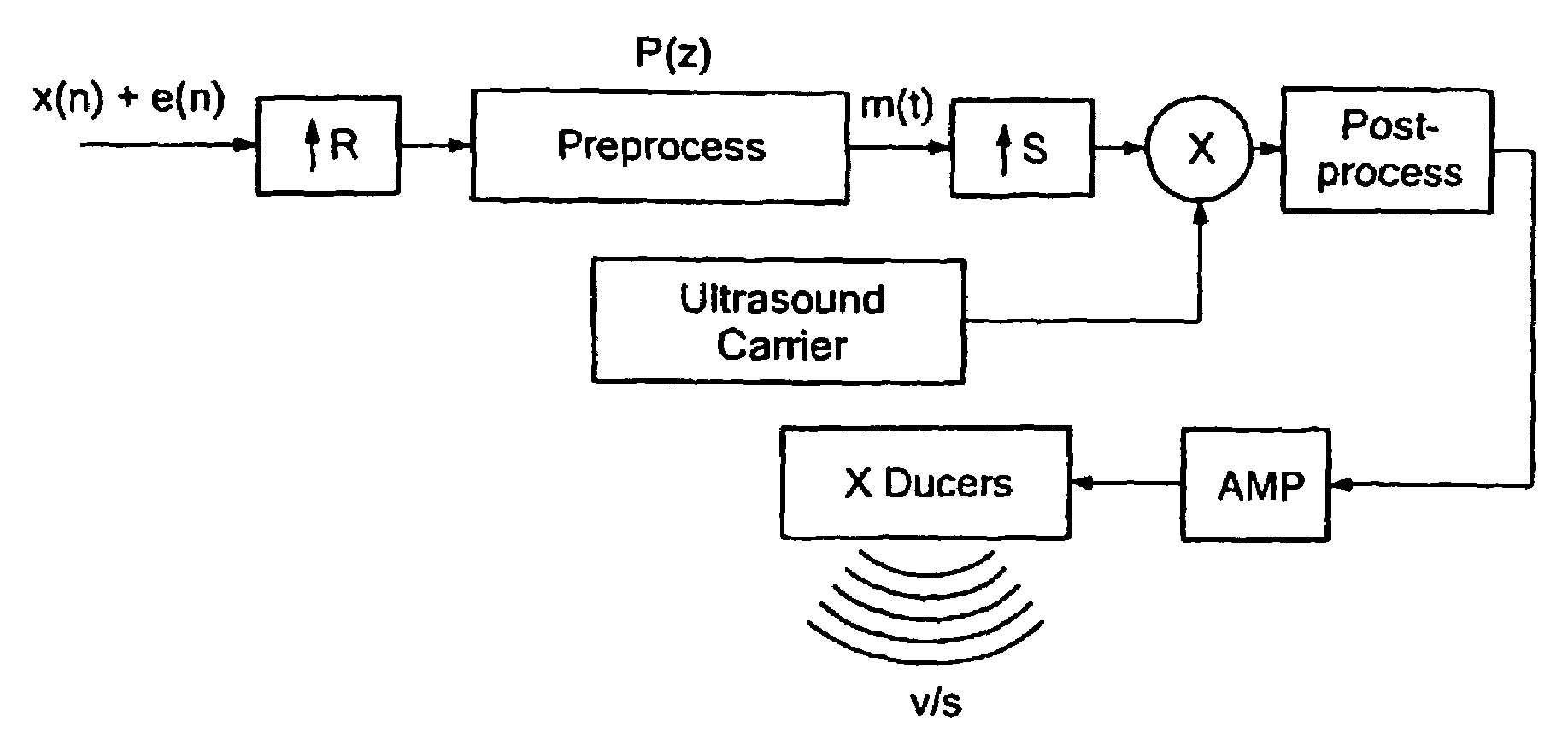
[0013]The generation of ultrasound from audible sound will in general require some step of modulation, which is simply a re-scaling of frequency. We can write this modulation step as:

p(t)=M(t)sin ωt

Where M(t) can be termed the modulation envelope, and ω is the carrier frequency. Basic parametric array theory predicts that, upon demodulation, the resulting audible sound q(t) is approximately proportional to the second derivative of the square of the modulation envelope:

q(t)∝d2 / dt2′(M2(t))

This function is an approximation, but serves well to illustrate the ideas contained herein.

[0014]We can define an arbitrary preprocessing function P{z}, which accepts some signal (primarily) in the audio range as input, and outputs a processed signal suitable for modulation oat the output. Thus, we generally have M(t)=P{z}, where z is some function of g(t). Note that the algorithm P{x} may also accept inputs such as environmental condition, listener position, desired sound quality, etc.

[0015]Early p...


PUM


Abstract

A system using the nonlinearity of a propagation medium to demodulate an ultrasonic wave having audio modulated onto the ultrasonic frequency, audio signal processing circuitry providing a delayed audio signal and an envelope signal which is a function of peaks of the audio signal over a predetermined interval. The delayed audio signal and the envelope signals are combined with the delay in the audio allowing the envelope signal to accurately be aligned with the audio signal in the combination.

Description

CROSS REFERENCE TO RELATED APPLICATIONS[0001]The present application incorporates by reference prior commonly owned U.S. Applications 60 / 185,235 filed Feb. 28, 2000; 60 / 406,230 filed Aug. 26, 2002; and Ser. No. 09 / 300,033.FIELD AND BACKGROUND OF THE INVENTION[0002]The parametric array uses the nonlinear response of a transmission medium such as air or water to convert or demodulate ultrasonic frequency waves into audio frequency waves of any audio frequency signals modulated onto the ultrasonic waves. This phenomenon is useful to direct a beam of ultra sound having audio modulated thereon to a specified region where it is demodulated in the medium and can be heard.[0003]In a typical case of a parametric array in air, the audible signal will typically be from voice, music or other normal audio frequency source. Prior to or subsequent to the conversion or modulation into the ultrasound frequency ranges, some form of signal processing is typically undertaken. This is undertaken to comp...

Claims


Application Information

Patent Timeline
Patent Type & Authority Patents(United States)
IPC IPC(8): H04B3/00G10K15/02H03D9/00H04B1/02H04B11/00
CPCG10K15/02H04B11/00H03D9/00
Inventor POMPEI, FRANK JOSEPH
Owner POMPEI FRANK JOSEPH
Why Eureka
Try Eureka