Method of manufacturing a quartz resonator

a manufacturing method and quartz resonator technology, applied in the direction of magnets, cores/yokes, magnetic bodies, etc., can solve the problems of fear of not being exposed to the extent of the lower layer of the resist film, no description of a solution, and the formation of unexposed portions, so as to minimize the lowering of the yield of the quartz resonator and reduce the shape of the crotch portion

Inactive Publication Date: 2009-10-06
NIHON DEMPA KOGYO CO LTD
View PDF7 Cites 6 Cited by
  • Summary
  • Abstract
  • Description
  • Claims
  • Application Information

AI Technical Summary

Benefits of technology

[0018]The object of the present invention in producing a tuning fork type quartz resonator from a quartz substrate is to provide a method of manufacturing a quartz resonator capable of suppressing short circuiting between excitation electrodes by restraining staying of a metal film in a crotch portion by controlling existence of resist reservoir in the crotch portion of the tuning fork when forming excitation electrodes on respective tuning fork arms by etching the metal film on the surface of the quartz resonator along a resist pattern formed on the surface thereof.
[0028]According to the present invention, after forming a quartz substrate by bonding two sheets of original plates which are made of quartz crystal, and of which main surfaces are orthogonal to the direction of the Z axis, the crystal axis, so that the plus / minus directions of each X axis, the crystal axis, are in a reverse relation to each other, etching is conducted from both front and back surfaces of the quartz substrate, and the outer shape formation of the quartz piece is conducted in a manner that the width direction thereof agrees with the X axis. Since the directions of the crystal axes are symmetrical between the front and the back of the quartz substrate formed in the manner described above, the etching progresses symmetrically with respect to the front and the back. Furthermore, since the difference in etching speed between axis directions toward +X and −X is small, the crotch portion between the vibrating arms of the quartz piece is formed in a cone shape in nearly symmetrical with respect to the front and the back, and bilaterally symmetrical, so that complication of the shape of the crotch portion is reduced. Accordingly, when a positive type resist is supplied on a metal film after the metal film to be an excitation electrode is formed in the areas including the side surfaces of the vibrating arms of the quartz piece, excessive resist flows down along the slope of the crotch portion, so that accumulation of the resist in the crotch portion is suppressed. Further, since complication of the shape is suppressed at the time of exposing the resist film thereafter, occurrence of unexposed portions on the surface of the crotch portion is suppressed. Accordingly, since staying of the resist film on the crotch portion after exposure and development is suppressed, it is possible to minimize lowering of yields of the quartz resonator caused by staying of the metal film below the resist film in the crotch portion without being removed to cause short circuit of the excitation electrodes on the right and left vibrating arms.

Problems solved by technology

The crotch portion 15, on which electrodes are not to be formed originally, is also exposed, but the resist film 16 is sometimes formed thick on the crotch portion 15 due to the accumulated resist as described above, which may result in occurrence of fear of not being exposed to the extent of the lower layer of the resist film 16.
In addition, there is a fear that unexposed portions are created because exposure beams are blocked at the crotch portion 15 due to its complicated shape.
Although the Patent Document 3 describes that the shape of the crotch portion of a tuning fork gets complicated by etching quartz, there is no description of a means to solve the problem described above.

Method used


Image

  • Method of manufacturing a quartz resonator
  • Method of manufacturing a quartz resonator
  • Method of manufacturing a quartz resonator

Examples


Embodiment Construction

)

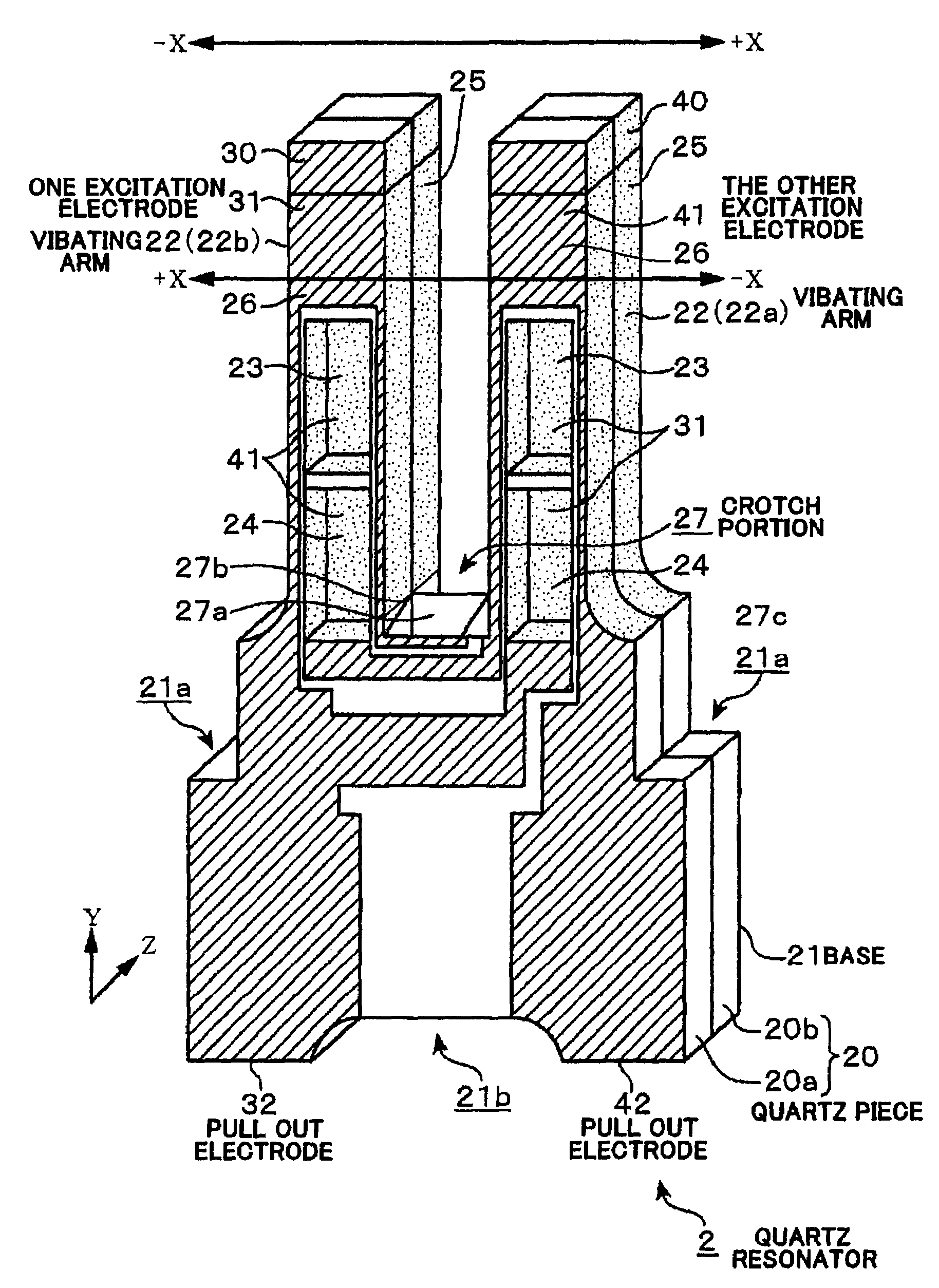
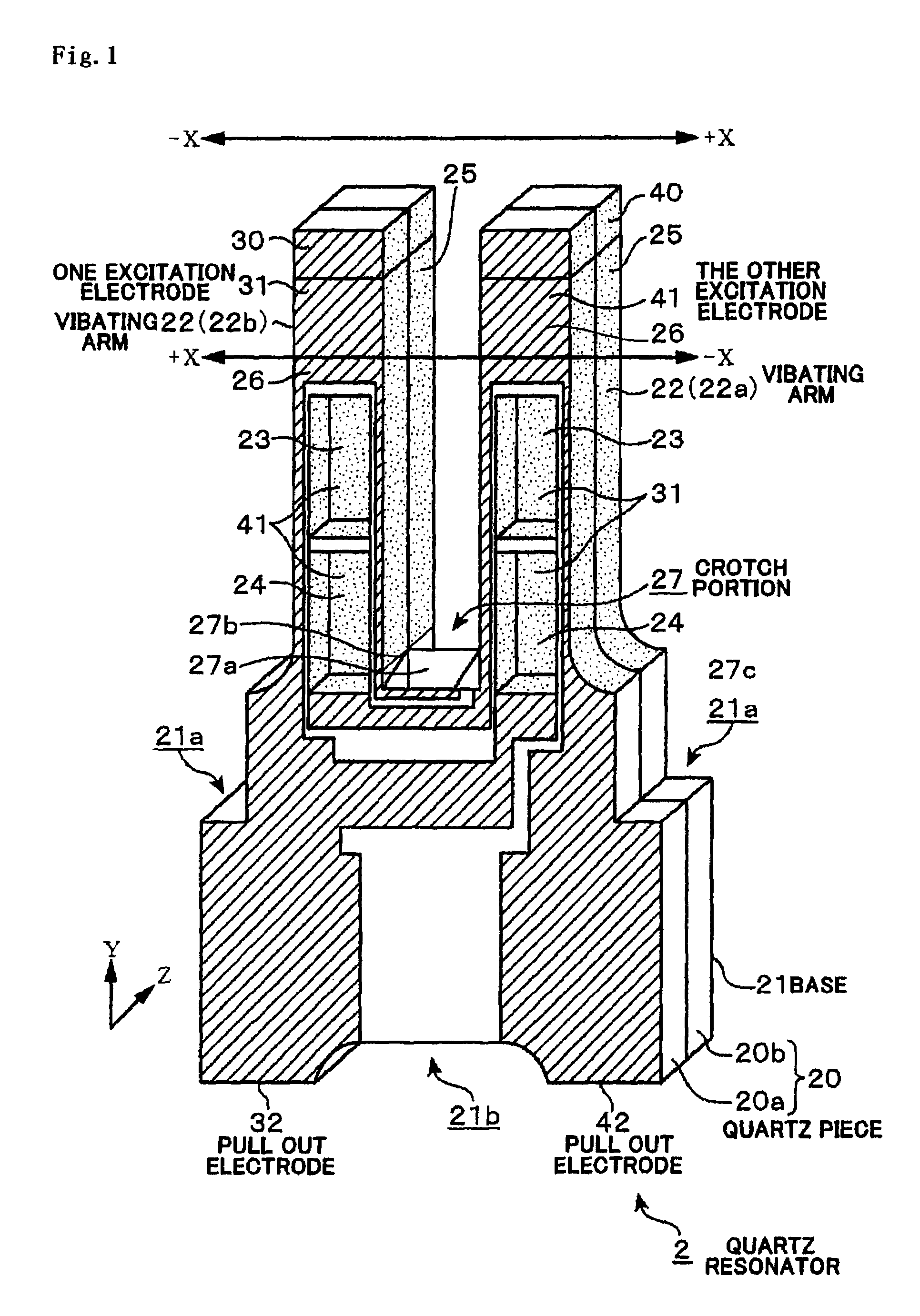
[0046]A method of manufacturing a tuning fork type quartz resonator, a piezoelectric oscillator, will be explained as an embodiment of the present invention. FIG. 1 is a perspective view of a quartz resonator 2 manufactured by this manufacturing method, wherein respective arrows, X, Y, and Z, in the drawing show the crystal axes of quartz crystal composing the quartz resonator 2 respectively. The quartz resonator 2 is formed such that respective directions of length, width, and thickness of the quartz resonator 2 are formed along the Y axis (mechanical axis), the X axis (electrical axis) and the Z axis (optical axis) of the quartz crystal, respectively.

[0047]The quartz resonator 2 is provided with a quartz piece 20, of which structure is nearly symmetrical with respect to the front and the back and bilaterally symmetrical. The quartz piece 20 is composed of two sheets of segments 20a and 20b, of which directions toward +X and −X are bilaterally opposite, and which are bonded to eac...


PUM

PropertyMeasurementUnit
transition temperatureaaaaaaaaaa
temperatureaaaaaaaaaa
widthaaaaaaaaaa

Abstract

The shape of a crotch portion of a tuning fork of a quartz piece is controlled such that main surfaces of two sheets of original plates, which are made of quartz crystal and the main surfaces thereof are orthogonal to the direction of the Z axis, which is a crystal axis, are bonded so that the plus / minus directions of the X axis, which is another crystal axis, are made in a reverse relation to each other to form a quartz substrate, and masks for forming the outer shape, through which the surfaces of the quartz substrate are exposed, are formed on both front and back surfaces of the quartz substrate in a manner that the mask follows along the outer shape of the quartz piece and the width direction of the outer shape agrees with the X axis, and the quartz substrate is etched to form the outer shape of the quartz piece.

Description

BACKGROUND OF THE INVENTION[0001]1. Field of the Invention[0002]The present invention relates to a method of manufacturing a tuning fork type quartz resonator, quartz resonators manufactured by the above method of manufacturing, and electronic parts including the quartz resonators.[0003]2. Description of the Related Art[0004]The tuning fork type quartz resonators have long been adopted as a signal source for pacing a wrist watch owing to its being compact, inexpensive and having a low power consumption, and the uses thereof are still expanding.[0005]FIG. 15 shows an example of the tuning fork type quartz resonators. In the drawing, the quartz resonator 1 is provided with a quartz piece (quartz blank) 10 including a base 11, two pieces (a pair) of vibrating arms 12 (12a and 12b) extending in parallel with each other leaving a space from the upper end side of the base 11.[0006]Both main faces of the vibrating arms 12a and 12b are provided with grooves 13 and 14 respectively, which ser...

Claims


Application Information

Patent Timeline
Patent Type & Authority Patents(United States)
IPC IPC(8): H04R31/00H03H3/02H03H9/19H03H9/215
CPCH03H3/02H03H9/215H03H2003/026Y10T29/49128Y10T29/42Y10T29/49135Y10T29/49005Y10T29/4908Y10T29/49133
Inventor TAKAHASHI, TAKEHIRO
Owner NIHON DEMPA KOGYO CO LTD
Why Eureka
Try Eureka