Image heating device and image forming apparatus

a heating device and heating device technology, applied in the direction of electrographic process apparatus, instruments, optics, etc., can solve the problems of abnormal change in element characteristics, increase in the number of conductors connected to the temperature detecting element, and decrease in the space between the conductors, so as to reduce the size of the heater, suppress short-circuiting, and improve the effect of voltage resistan

Active Publication Date: 2020-09-24
CANON KK
View PDF0 Cites 0 Cited by
  • Summary
  • Abstract
  • Description
  • Claims
  • Application Information

AI Technical Summary

Benefits of technology

[0023]According to the present invention, it is possible to reduce the size of the heater while suppressing short-circuiting, migration, and poor voltage resistance between adjacent conductors.

Problems solved by technology

However, as the number of temperature detecting elements formed on a ceramic substrate increases, the number of conductors connected to the temperature detecting element increases, and the space between the conductors becomes smaller in the ceramic substrate of a limited size.
Furthermore, when connecting a conductor to an element or metal such as a temperature detecting element or an electrode, the conductor material to be used needs to be changed depending on the compatibility of the conductor material of the conductor and the element or metal to be connected thereto (abnormal change in element characteristics, poor contact, and the like).
When the conductor material to be used is expensive, a conductor pattern is formed of two or more types of conductor materials, and a distance between adjacent conductors cannot be ensured due to a displacement occurring when forming each conductor.
Where an appropriate distance cannot be ensured between adjacent conductors, there is a concern that problems such as short-circuiting, migration, and poor voltage resistance between adjacent conductors may occur.

Method used


Image

  • Image heating device and image forming apparatus
  • Image heating device and image forming apparatus
  • Image heating device and image forming apparatus

Examples


embodiment 1

1. Configuration of Image Forming Apparatus

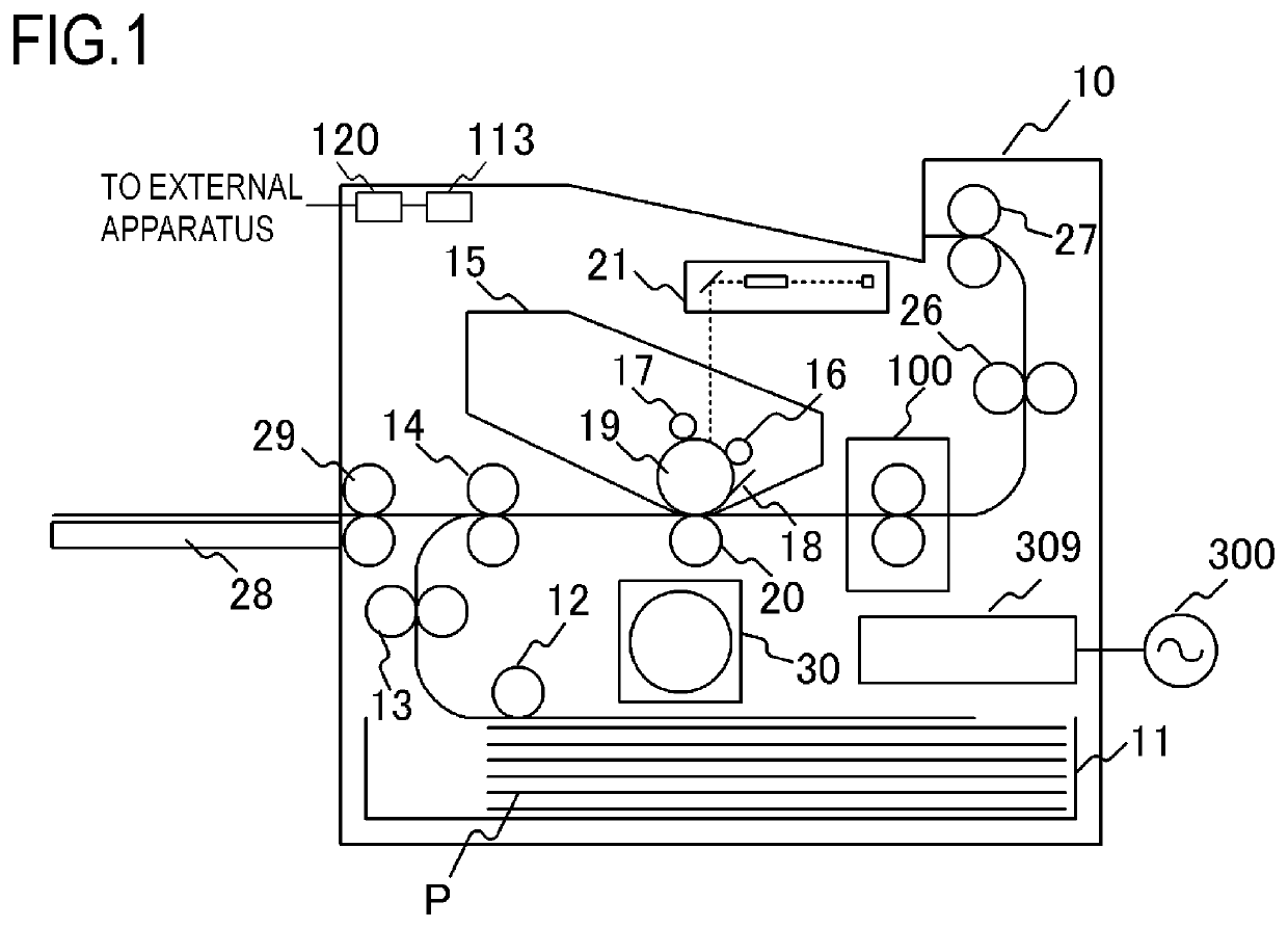
[0034]FIG. 1 is a schematic sectional view of the image forming apparatus according to an embodiment of the present invention. Examples of the image forming apparatus to which the present invention is applicable include a copying machine, a printer and the like using an electrophotographic method or an electrostatic recording method. Here, a case is described in which the present invention is applied to a laser printer in which an image is formed on a recording material P by using an electrophotographic method.

[0035]An image forming apparatus 10 includes a video controller 120 and a control unit 113. The video controller 120 serves as an acquisition unit for acquiring information on an image formed on a recording material and receives and processes image information and a print instruction transmitted from an external device such as a personal computer. The control unit 113 is connected to the video controller 120, and controls each unit co...

embodiment 2

[0066]Embodiment 2 of the present invention will be described with reference to FIG. 7. Here, only differences between Embodiment 2 and Embodiment 1 will be described. In Embodiment 2, description of items common to Embodiment 1 will be omitted.

[0067]Embodiment 2 is configured, similarly to Embodiment 1, so that a portion of the conductor A having the width W2 in the overlapped portion of the conductor group A and the conductor group B is smaller than the portions of the conductor groups A, B having the width W1, W3. In the configuration of Embodiment 2, by contrast with Embodiment 1, each conductor in the conductor group A has a tapered portion that extends continuously and gradually narrows from the end part of the portion having the width W1 in the conductor, which faces the terminal of the conductor group B, toward the terminal of the conductor group B. The tapered portion has a portion having a width W2 in the middle thereof, and is configured to overlap with each conductor of ...

embodiment 3

[0070]Embodiment 3 of the present invention will be described with reference to FIGS. 8A to 8C. Here, only features in Embodiment 3 that are different from those of the abovementioned embodiments will be described. In Embodiment 3, description of items common to the abovementioned embodiments will be omitted.

[0071]Embodiment 3 is configured, similarly to Embodiments 1 and 2, so that the width W2 of the conductor A in the overlapped portion of the conductor A and the conductor B is smaller than the widths W1, W3 in the conductors A, B. Further, the conductor group B is formed by printing at a conductor interval of a distance W4. The configuration of Embodiment 3 differs from those of Embodiments 1 and 2 in that the conductor group B is overlapped (covered) with glass 700 as an insulating protective layer.

[0072]The configuration of Embodiment 3 will be described with reference to FIGS. 8A to 8C. From the viewpoint of cost, silver (Ag) is selected as the conductor material to be used f...


PUM

PropertyMeasurementUnit
width W1aaaaaaaaaa
width W2aaaaaaaaaa
width W3aaaaaaaaaa

Abstract

A plurality of electric conductors provided on a substrate of a heater of an image heating device has a conductor group A including a plurality of first electric conductors and a conductor group B including a plurality of second electric conductors. The plurality of first electric conductors each have a first portion having a width W1 and a second portion having a width W2 smaller than the width W1, are provided on the substrate to be arranged side by side in a width direction. The plurality of second electric conductors each have a width W3 larger than the width W2, are provided on the substrate to be arranged side by side in a width direction so as to partially overlap the second portion.

Description

BACKGROUND OF THE INVENTIONField of the Invention[0001]The present invention relates to an image heating device such as a fixing device installed in an image forming apparatus such as a copying machine or a printer using an electrophotographic method or an electrostatic recording method, a gloss-imparting device that increases the gloss of a toner image by reheating the fixed toner image on a recording material, and the like.Description of the Related Art[0002]A conventional image heating device provided in an image forming apparatus includes a tubular film called an endless belt or an endless film, a flat heater in contact with an inner surface of the film, and a roller for forming, together with the heater, a nip portion through the film. The heater of this image heating device is configured of an insulating ceramic substrate, a heating resistor formed by printing on the substrate, and a temperature detecting element. A configuration in which power supply to a heating resistor is ...

Claims


Application Information

Patent Timeline
Patent Type & Authority Applications(United States)
IPC IPC(8): G03G15/20
CPCG03G15/2053G03G15/2042G03G2215/2025G03G15/2064G03G2215/2035
Inventor NAKASHIMA, YUSUKENAMIKI, TERUHIKOKAWAZU, TAKAOOGURA, RYOTA
Owner CANON KK
Why Eureka
Try Eureka