Rubber product-reinforcing metallic cord and method for manufacturing such a cord

a technology of reinforced metallic cords and rubber products, which is applied in the direction of yarn, transportation and packaging, tyre parts, etc., can solve the problems of less resistance to compressive loads, lowering the compressive rigidity of the cord, and conflicting requirements above two requirements, so as to achieve smooth and sufficient penetration into the cord, low facility and production costs, and high compressive rigidity

Inactive Publication Date: 2009-10-06
SUMITOMO (SEI) STEEL WIRE CORP +1
View PDF24 Cites 0 Cited by
  • Summary
  • Abstract
  • Description
  • Claims
  • Application Information

AI Technical Summary

Benefits of technology

[0030]The metallic cord according to this invention comprises the abovementioned first pre-strand, and the second pre-strand and / or the fifth metallic filament. The second and / or fourth filament, which is helically wrapped around the first and / or third filament, serves as a spacer that ensures the formation of gaps between the metallic filaments into which rubber can penetrate without the need to corrugate any metallic filament. Thus, rubber can smoothly and sufficiently penetrate into the cord according to the invention. Still, the cord of the invention maintains high compressive rigidity.
[0031]The second and / or fourth metallic filament can be helically wrapped around the first and / or third metallic filament with a simple filament supply unit and a flyer. Only one twister is needed. The cord according to the present invention can thus be manufactured at low facility and production costs.

Problems solved by technology

But in today's such reinforcing metallic cords, the above two requirements tend to conflict each other.
These portions are less resistant to compressive loads, thus lowering the compressive rigidity of the cord.
This increases the facility cost and manufacturing cost.
This may cause adjacent cords to contact each other when they are set in rubber to reinforce the rubber, because they have a tendency to curl and are unstable.

Method used


Image

  • Rubber product-reinforcing metallic cord and method for manufacturing such a cord
  • Rubber product-reinforcing metallic cord and method for manufacturing such a cord
  • Rubber product-reinforcing metallic cord and method for manufacturing such a cord

Examples


first embodiment

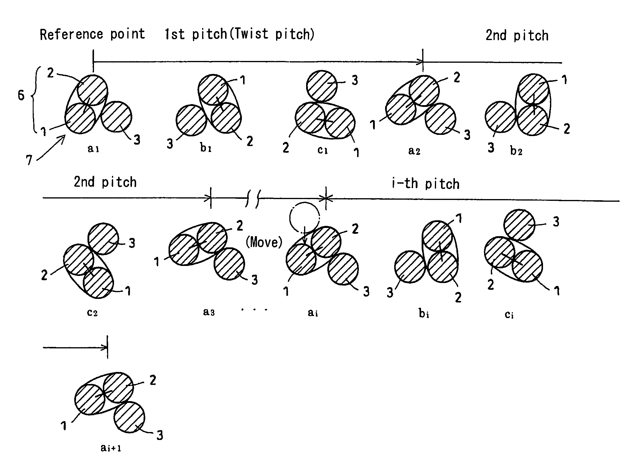
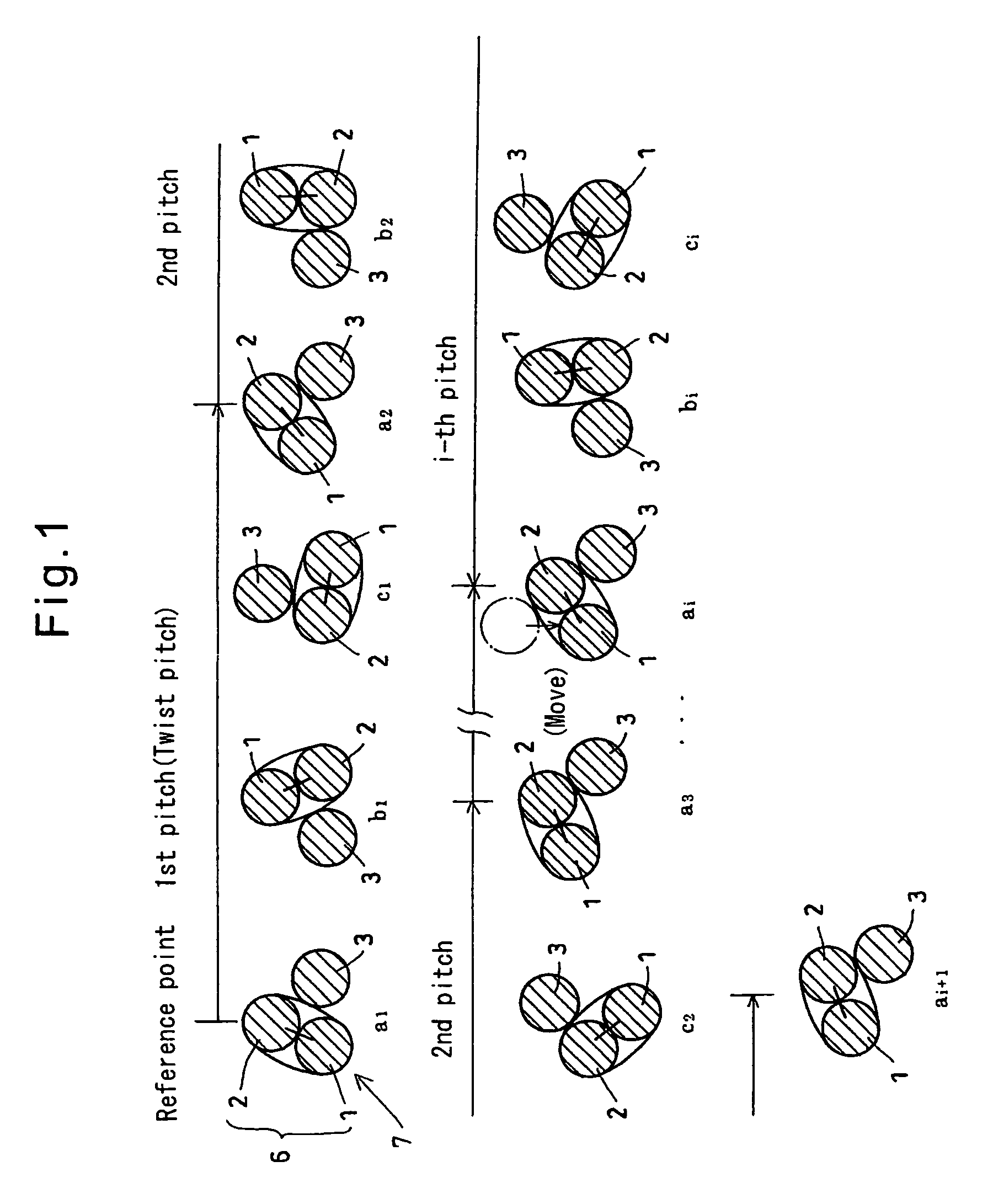
[0064]Now the embodiments of this invention are described with reference to FIGS. 1 to 7. FIG. 1 schematically shows cross-sections of a rubber product-reinforcing metallic cord 7 of the first embodiment which are taken along planes longitudinally separated from each other by a distance of ⅓P (P=twist pitch of the cord). The cord of this embodiment may be twisted in the pattern of the letter Z. But the cord shown and described is twisted in the pattern of the letter S.

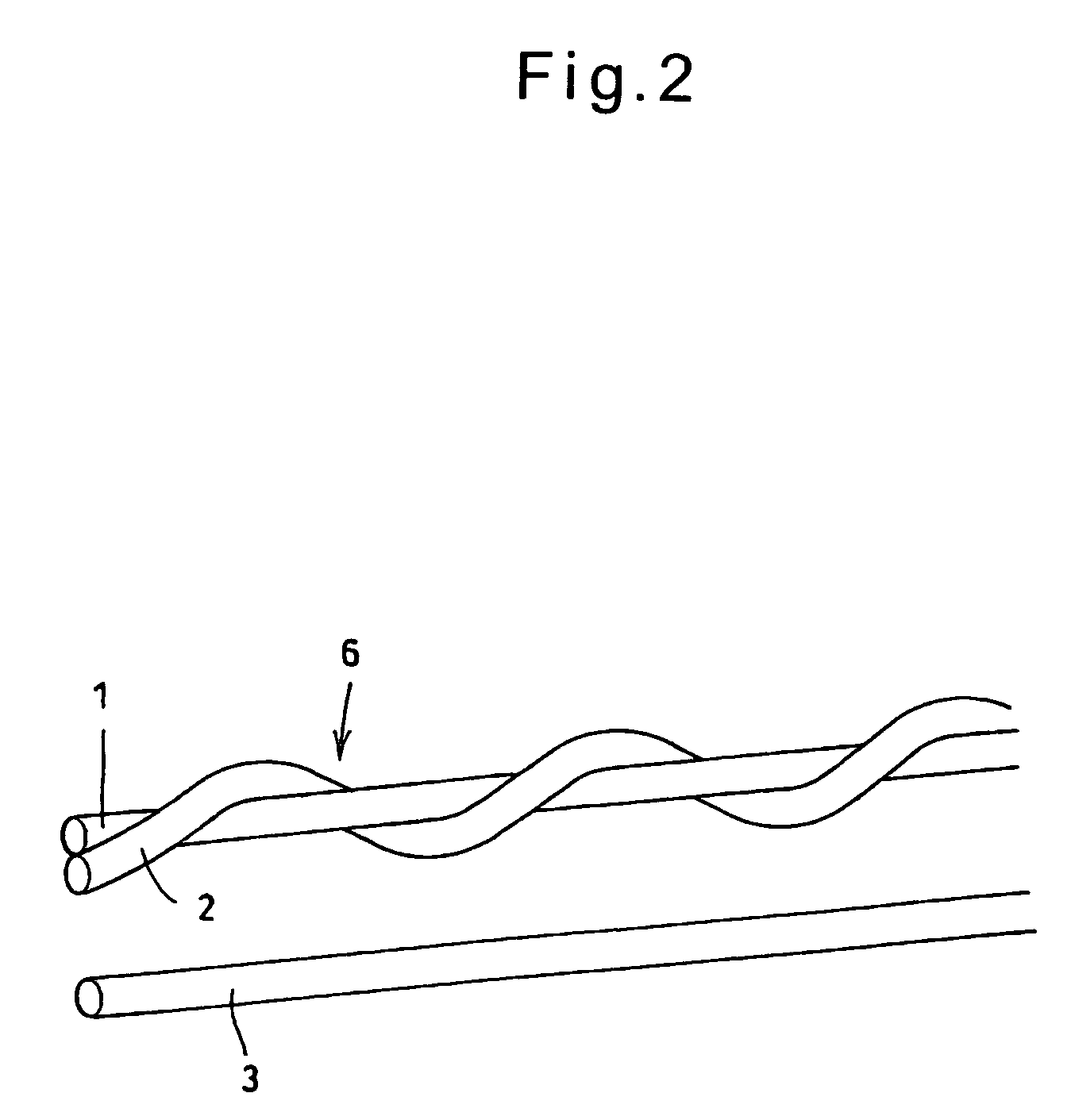
[0065]As shown in FIG. 2, the metallic cord 7 is formed by helically wrapping a metallic filament 2 around a metallic filament 1 to form a pre-strand 6, and twisting together the pre-strand 6 and another metallic filament 3. If plated steel filaments are used as the filaments 1 to 3, the cord will be a steel cord. But the cord according to the present invention is not limited to a steel cord.

[0066]Because the pre-strand 6 and the filament 3 are three-dimensionally twisted in the pattern of the letter S, and the metalli...

second embodiment

[0070]As shown in FIG. 4, the metallic cord 8 of the second embodiment is formed by helically wrapping a metallic filament 2 around a metallic filament 1 to form a pre-strand 6a1, helically wrapping a metallic filament 4 around a metallic filament 3 to form a pre-strand 6a2, and twisting together the pre-strands 6a1 and 6a2 with a pitch P.

[0071]If plated steel filaments are used as the filaments 1 to 4, the cord will be a steel cord. But the cord according to the present invention is not limited to a steel cord.

[0072]Because the pre-strands 6a1 and 6a2 are three-dimensionally twisted in the pattern of the letter S, and the metallic filaments 2 and 4 are further wrapped around the metallic filaments 1 and 3, respectively, the metallic filaments 2 and 4 act as a spacer to define suitable gaps between the respective metallic filaments. The gaps improve the degree of penetration of rubber into the cord.

[0073]Each filament is not corrugated or otherwise irregularly preshaped, so that the...


PUM

PropertyMeasurementUnit
twist angleaaaaaaaaaa
tensionaaaaaaaaaa

Abstract

A rubber product-reinforcing metallic cord is provided which comprises three to five metallic filaments, which shows a high degree of penetration of rubber without reducing compressive rigidity, and which can be manufactured at low facility and production costs. A rubber product-reinforcing metallic cord 7 is formed by twisting together a pre-strand 6 comprising a first metallic filament 1 and a second metallic filament 2 helically wrapped around the first filament 1, and a fifth metallic filament 3 (or 5) with a twist pitch P. The metallic cord 7 may be formed by twisting together two of such pre-strands, or by twisting together two of such pre-strands and the fifth metallic filament.

Description

RELATED APPLICATION[0001]This application is a national phase of PCT / JP2005 / 006855 filed on Apr. 7, 2005, which claims priority from Japanese Application Nos. JP 2004-113896, JP 2004-114112, and JP 2005-065823 filed on Apr. 8, 2004, Apr. 8, 2004, and Mar. 9, 2005, respectively, the disclosures of which Applications are incorporated by reference herein. The benefit of the filing and priority dates of the International and Japanese Applications is respectfully requested.TECHNICAL FIELD[0002]The present invention relates to an inexpensive metallic cord for reinforcing rubber products that allows smooth penetration of rubber into the cord while maintaining high compressive rigidity, and a method for manufacturing such a cord.BACKGROUND ART[0003]Two major requirements for reinforcing metallic cords used in vehicle tires are a high degree of penetration of rubber and high compressive rigidity, the latter having an influence on the cornering performance of the vehicle. But in today's such ...

Claims


Application Information

Patent Timeline
Patent Type & Authority Patents(United States)
IPC IPC(8): D02G3/22D02G3/48B60C9/00D07B1/06D07B3/10
CPCB60C9/0007D07B1/0613D07B1/062D07B3/02D07B3/10D07B2501/2046D07B2201/104D07B2201/2023D07B2201/2024D07B2201/2038D07B2207/205D07B2207/4009D07B2207/4013D07B2801/12D07B1/06B60C9/00
Inventor OKAMOTO, KENICHISAKAI, YASUOSAITO, KAZUHIKO
Owner SUMITOMO (SEI) STEEL WIRE CORP
Why Eureka
Try Eureka